133
CFW-08 OPTIONS AND ACCESSORIES
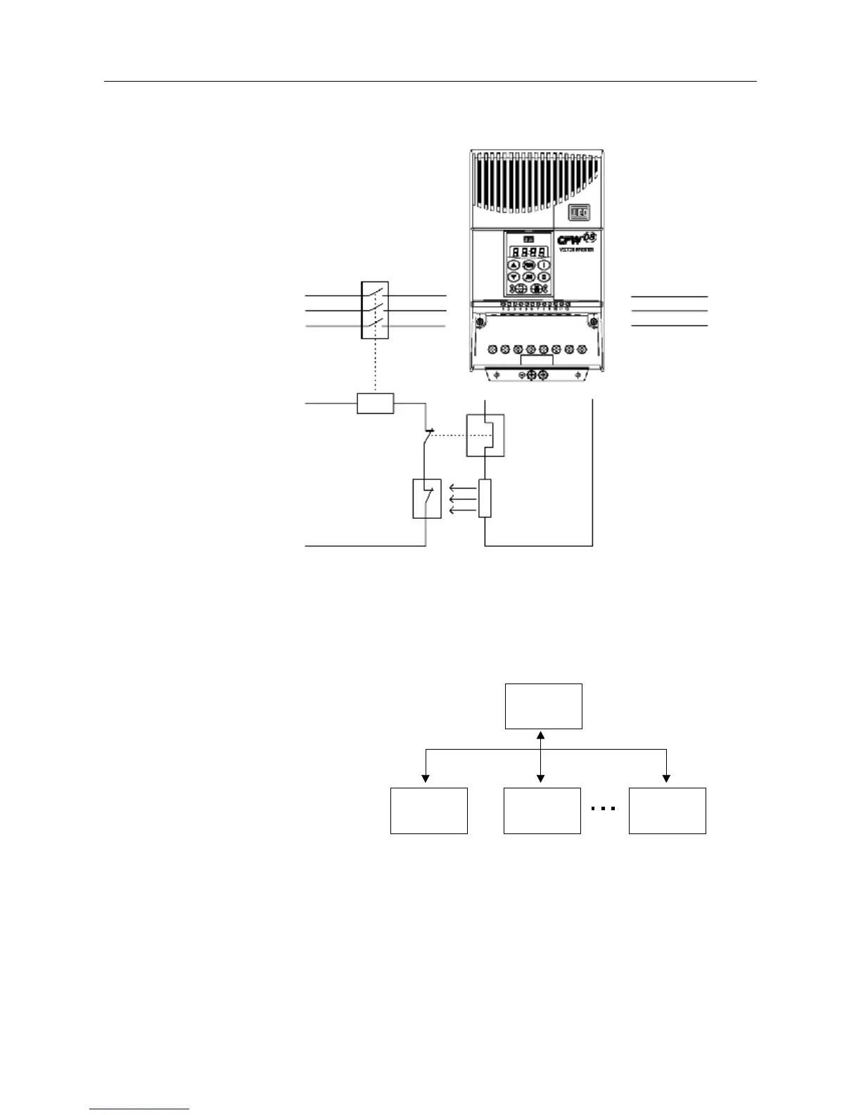
Figure 8.23 - Braking resistor connection
(only for models 7.3-10-16A/200-240V e 2.7-4.3-6.5-10-13-16/380-480V)
8.19 SERIAL
COMMUNICATION
MOTOR
POWER
SUPPLY
CONTACTOR
CONTROL POWER
SUPPLY
OVERLOAD
RELAY
THERMOSTAT
BRAKING
RESISTOR
U
V
W
R
S
T
BR +UD
Master PC, PLC, etc.
Slave 1
(Inverter)
Slave 2
(Inverter)
Slave n
(Inverter)
n ≤ 30 for WEG Protocol
n ≤ 247 for Modbus-RTU
8.19.1 Introduction
The basic objective of the serial communication is the physical connection
of the inverters in an equipment network configured as follows:
The inverters have a control software for data transmission/reception through
serial interface, thus facilitating the reception of data that have been sent
by the master and the transmission of the data requested by the master.
This software supports WEG protocol and nine different Modbus-RTU
modes, that can be selected via parameter P312. The subjects broached
in this Section refers to WEG protocol. For more details about the Modbus-
RTU, see item 8.19.
The transfer rate is 9600 bits/s, following an exchange protocol of question/
answer typeby using ASCII characters.
The master is able to realize the following operations related to each
inverter: