136
CFW-08 OPTIONS AND ACCESSORIES
In this case we have the connection of a master to an inverter (point-to-
point). The data can be exchanged in a bi-directional way, but not
simultaneously (HALF DUPLEX).
The logical levels meet the EIA RS-232C STANDARD, that specifies the
use of balanced signals. In this case one wire is used for the transmission
(TX), one wire for the reception (RX) and one wire for the return (0V).This
configuration is a three wire economy model.
You must use the RS-232 (KCS-CFW08) module in the inverter (refer to
Section 8.9).
8.19.2.2 RS-232
8.19.3 Definitions
The tems of this Section describe the protocol used in the serial
communication.
8.19.3.1 Used Terms
Parameters: are those existing in the inverters whose visualization or
alteration is possible through the keypad (HMI) interface.
Variables: are values that have specific inverter functions and that can
be read and, in some cases, modified by the master.
Basic variables: are those that can be accessed only through the
serial interface.
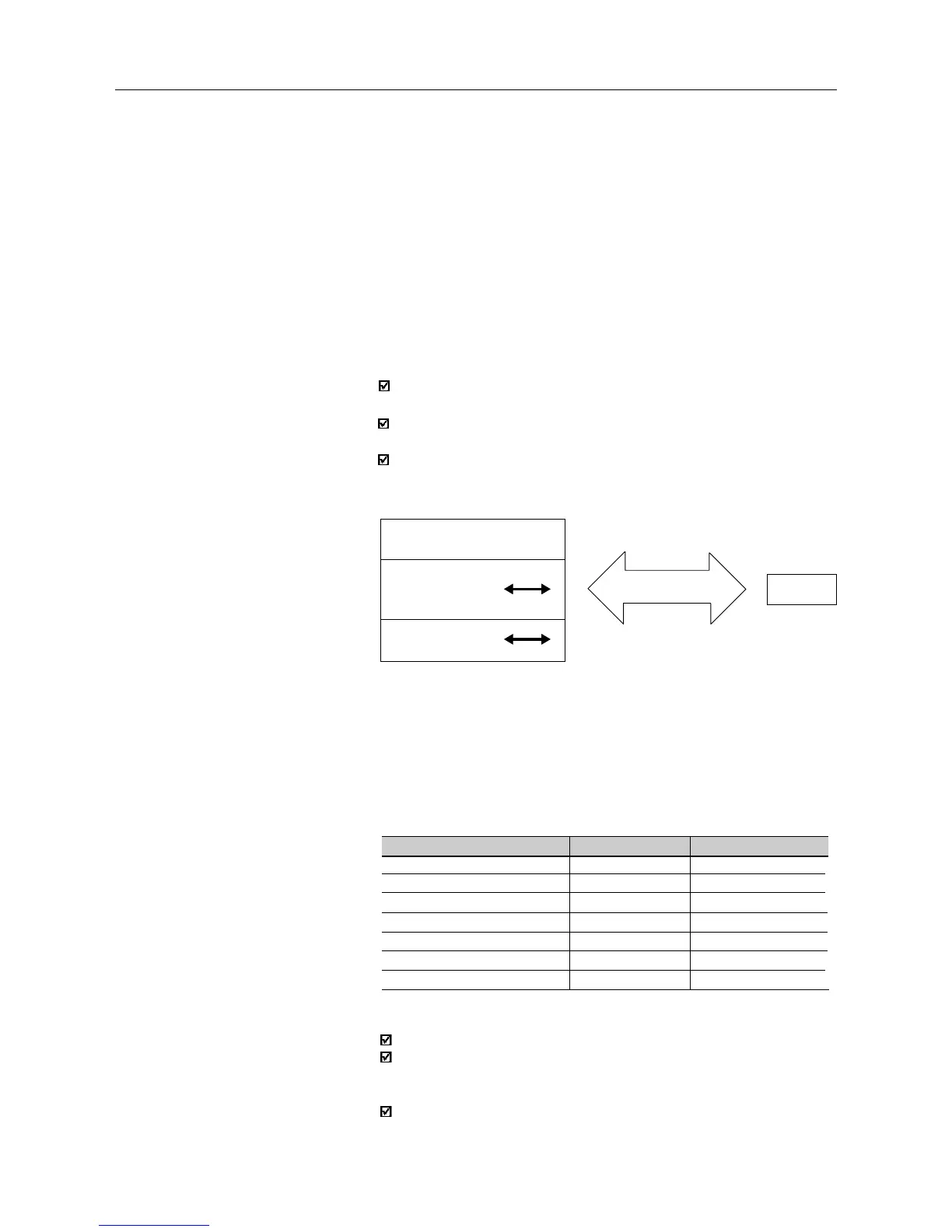
SCHEMATIC DIAGRAM:
INVERTER
BASIC
VARIABLES
PARAMETERS
MASTER
SERIAL CONNECTION
VARIABLES
8.19.3.2 Parameter/Variables
Resolution
1 start bit;
8 information bits [they codify text characters and transmission
characters, removed from the 7 bits code, according to ISO 646 and
complemented for the even parity (eighth bit)];
1 stop bit.
After the start bit, follows the less significant bit:
8.19.3.3 Character Format
Unit
H
A
V
s
%
-
RPM
Resolution
0.01Hz/unit
0.01A/unit
1V/unit
0.1s/unit
0.01%/unit
0.01/unit
1RPM/unit
Parameter
Frequency
Current (AC or DC)
Voltage (AC or DC)
Time
Percentage
Gain
RPM
The variables and the parameters have 16 bits format, i. e., from -32767 to
+32768 for signed variables or from 0 to 65535 for unsigned variables.
All variables are considered as signed variables, except those related to
time (time, period, frequency, ...)
In addition, the maximum and minimum values must consider the
parameter range limits.
The below shows the main variables and their respective resolutions.