38
INSTALLATION AND CONNECTION
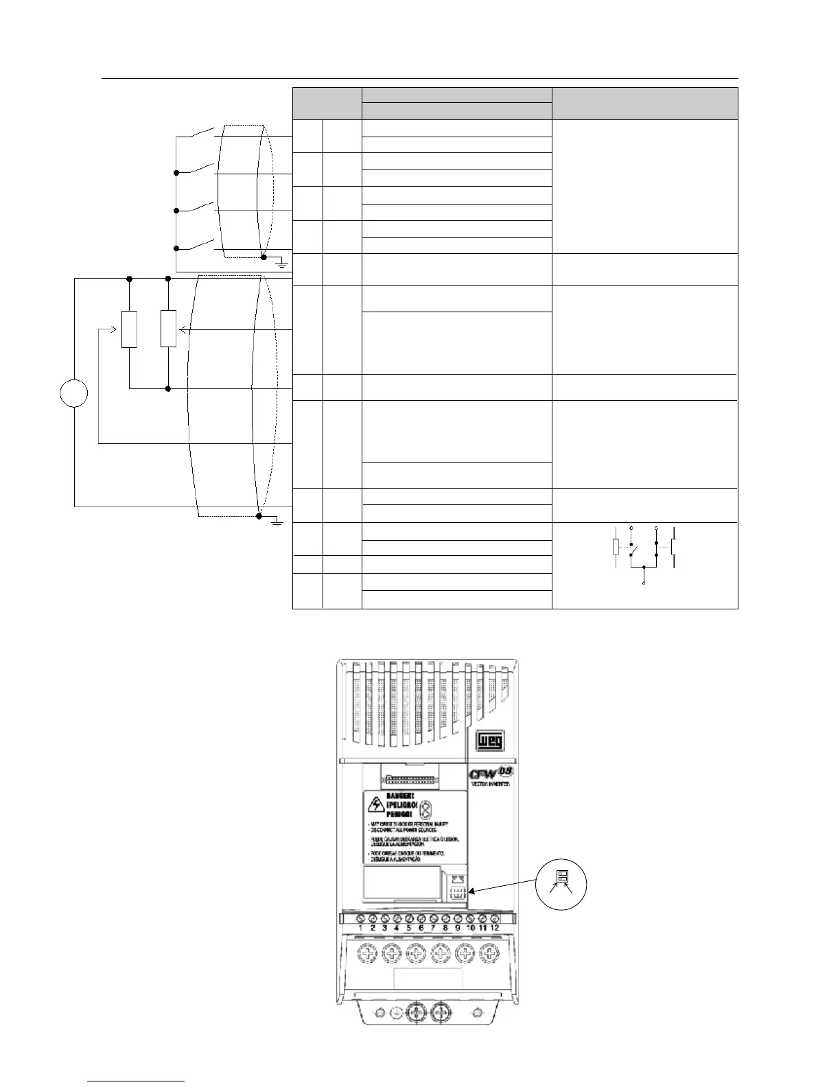
Figure 3.9 - XC1 control terminal description of the control board 1 (CFW-08 Plus)
Figure 3.10 - Dip switch position for 0 ...10V/4 ... 20mA selection
S1
2
1
OFF
ON
Conector XC1
1 DI1
2 DI2
3 DI3
4 DI4
5 GND
6 AI1
7 +10V
8 AI2
9AO
10 NF
11 Comum
12 NA
Description
Factory Default Function
Digital Input 1
General Enable (remote mode)
Digital Input 2
FWD / REV (remote mode)
Digital Input 3
Reset
Digital Input 4
Start/Stop (remote mode)
0V Reference
Analog input 1
Frequency/Speed reference (remote mode)
Potentiometer reference
Analog input 2
Not used
Analog output
Output Frequency (Fs)
Relay Output 2 - NC contact
Fs>Fx
Relay outputs common points
Relay Output 1 - NO contact
No Fault
Specifications
4 isolated digital inputs
Minimum High Level: 10VDC
Maximum Low Level: 3VDC
Input Current: -11mA @ 0V
Max. Input Current: -20 mA
Not connected to PE
0 to 10VDC or 0(4) to 20mA (fig. 3.10).
Impedance: 100kΩ (0...10V input), 500Ω
(0/4...20mA input).
Resolution: 7bits.
Max. input voltage: 30VDC
+10VDC,
±
5%, capacity: 2mA
0 to 10VDC or 0(4) to 20mA (fig. 3.10).
Impedance: 100kΩ (0...10V input), 500Ω
(0/4...20mA input).
Resolution: 7bits.
Max. input voltage: 30Vdc
0 to 10VDC, RL ≥ 10k Ω
Resolution: 8bits
Contact capacity:
0.5A / 250VAC
CW
CCW
≥
10k
Ω
RPM
-
+
Relé 1
11
Relé 2
12 10
CCW
CW
≥
10k
Ω