39
INSTALLATION AND CONNECTION
Analog Input
AI1
AI2
Factory Deafult Setting
Frequency / Speed
Reference (remote mode)
No function
Dip
Switch
S1.1
S1.2
Selection
OFF: 0 ... 10V
ON: 4 ... 20mA or 0 ... 20mA
OFF: 0 ... 10V
ON: 4 ... 20mA or 0 ... 20mA
Table 3.5 - Dip switch configuration
NOTE!
Jumpers S1 are factory set to OFF position (0 ... 10V signal).
If it's used a 4 ... 20mA signal, set parameter P235 and/or P239, that
defines the signal type at AI1 and AI2, respectively.
The parameters related to the analog inputs are: P221, P222, P234,
P235, P236, P238, P239 e P240. For more details, please refer to
Chapter 6.
During the signal and control wire installation note please the following:
1) Cable cross section: 20 ... 14 AWG (0.5...1.5mm²).
2) Max. Torque: 0.50 N.m (4.50 lbf.in).
3) XC1 wiring must connected with shielded cables and installed
separately at a distance of 10 cm each other for lengths up to 100m
and at distance of 25cm each other for lengths over 100m. If the crossing
of these cables is unavoidable, install them perpendicular, maintaining
a mimimum separation distance of 2 in (5 cm) at the crossing point.
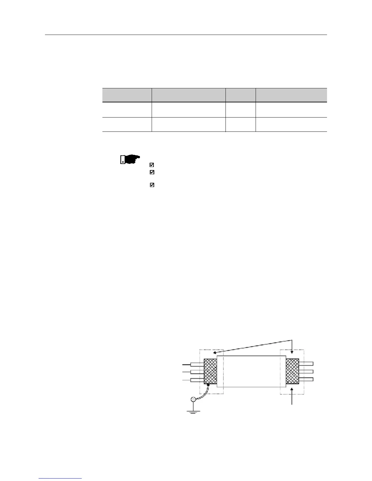
Connect the shield as shown below:
Figure 3.11 - Shield connection
Connect to earth: bolts are located on heatsink
Do not
ground
Inverter
side
Insulate with tape
4) For wiring distances longer than 150 ft ( 50 m), it's necessary to use
galvanic isolators for the XC1:5...9 analog signals.
As a default the analog input(s) is(are) selected as 0...10V. This can be
changed using dip switch S1 on the control board and parameters P235
and P239 (see note below).