23
GENERAL INFORMATION
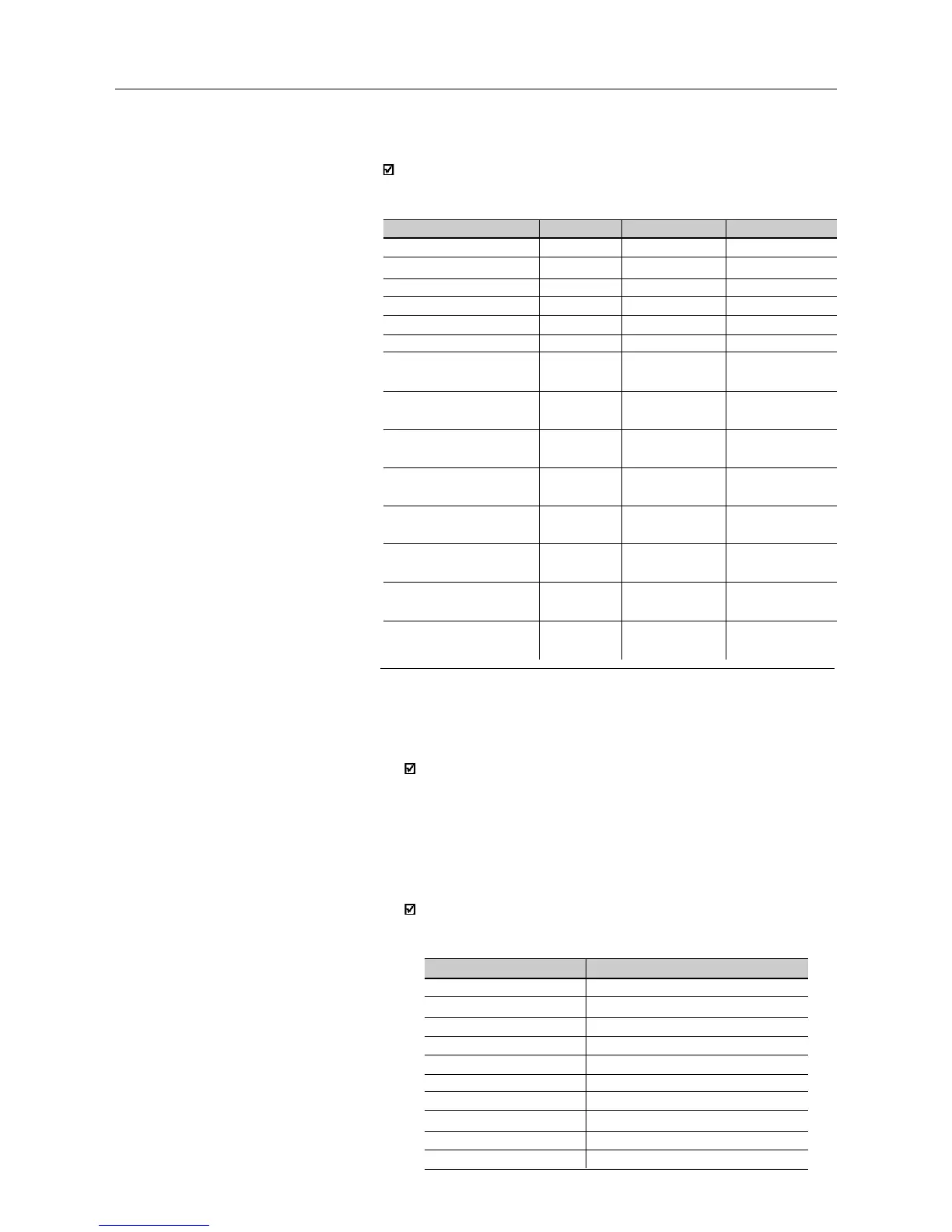
I/O
Digital Input DI1
Digital Input DI2
Digital Input DI3
Digital Input DI4
0V for Digital Inputs
+10V
Analog Input AI1 -
voltage signal
Analog Input AI1 -
current signal
0V for analog
input(s)
Analog Input AI2 -
voltage signal
Analog Input AI2 -
current signal
Saída Analógica AO
Relay Ouput RL1
Relay Output RL2
µline
1
2
3
4
5
6
7
9
8
not
available
not
available
not
availablel
10(NF), 11(C)
and 12(NA)
not
available
CFW-08
1
2
3
4
5
6
7 with switch
S1:1 at pos. OFF
7 with switch
S1:1 at pos. ON
5
not
available
not
available
not
available
10(NF), 11(C)
and 12(NA)
not
available
CFW-08 Plus
1
2
3
4
5
6
7 with switch S1:1
at position OFF
7 with switch S1:1
at position ON
5
8 with switch S1:2
at position OFF
8 with switch S1:2
at position ON
9
11-12(NO)
10-11(NC)
Parameters and Functions
Parameters that are already used in
µµ
µµ
µline but have been changed
a) P136 - Manual Torque Boost (IxR Compensation)
Besides the parameter name, also the way the user enters the IxR
compensation value has been changed. In the old µline, the
parameter P136 had a family of 10 curves (value range: 0 to
9). In the new CFW-08, the IxR Compensation is set by entering a
percent (relating to the input voltage) that defines the output voltage
for an output frequency equal to zero. So larger curve set and a
larger variation range is obtained.
Table below shows the equivalence between which was programmed
in the old µline and which must be programmed in the new CFW-
08 to obtain the same result.
P136 set in µline
0
1
2
3
4
5
6
7
8
9
P136 to be set in the CFW-08
0.0
2.5
5.0
7.5
10.0
12.5
15.0
17.5
20.0
22.5
But the control connections (terminals XC1) differ between the µline
and the CFW-08 line. Table below shows theses pin differences: