EasyManua.ls Logo

WEIHONG NK105G3 User Manual

Default Icon
104 pages
To Next Page IconTo Next Page
Page #1 background imageLoading...
Page #1 background image
上海维宏电子科技股份有限公司
SHANGHAI WEIHONG ELECTRONIC TECHNOLOGY CO., LTD.
Manufacturer Manual of NK105 Integrated CNC System
(Applicable to NK105G3 Handheld Box)
Version: 2020.5 1st Version
Author: Product Supporting Department
Weihong Corporation, All Rights Reserved
1 System overview................................................................................................................................................. 1
1.1 NK105 (E) Control Box with Four Axes ................................................................................. 1
1.1.1 Schematic Diagram .............................................................................................................. 2
1.1.2 Dimension Drawing (Unit: mm) .................................................................................. 3
1.2 NK105G3 Handheld Box.................................................................................................................. 3
1.2.1 Button Definition................................................................................................................... 4
1.2.2 Dimension Drawing (Unit: mm) ............................................................................... 10
1.3 Main Software Interface ............................................................................................................... 10
1.3.1 General NK105 with Four Axes ................................................................................. 11
1.3.2 General NK105 with Double Z Axes ....................................................................... 12
2 Wiring ..................................................................................................................................................................... 13
2.1 Signal Type ........................................................................................................................................... 13
2.1.1 Binary Input Signal ........................................................................................................... 13
2.1.2 Open Collector Output Signal ..................................................................................... 14
2.1.3 Analog Output Signal ....................................................................................................... 14
2.1.4 Differential Output Signal ............................................................................................. 15
2.2 Terminal Definition ......................................................................................................................... 15
3 Basic Commissioning .................................................................................................................................... 16
3.1 Start the System................................................................................................................................. 16
3.2 Select the Axis Mode ....................................................................................................................... 17

Table of Contents

Question and Answer IconNeed help?

Do you have a question about the WEIHONG NK105G3 and is the answer not in the manual?

WEIHONG NK105G3 Specifications

General IconGeneral
Control axes3
Minimum input unit0.001mm
Operating temperature0°C to 45°C
Storage temperature-20°C to 60°C
Cooling MethodNatural cooling
Maximum speed24m/min
Output Voltage24VDC

Summary

System Overview

General NK105 with Four Axes

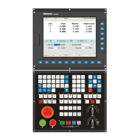
Explains the main interface for NK105 with four axes, including activated axes and status indicators.

General NK105 with Double Z Axes

Details the main interface for NK105 with double Z axes, including axes, coordinates, and status.

Basic Commissioning

Adjust the Port Polarity

Procedure to adjust input/output port polarities based on switch type.

Set Pulse Equivalent

Instructions on setting pulse equivalent for accurate machine tool control.

Adjust the Axis Direction

Procedure to check and adjust axis direction for correct machine operation.

Set the Workbench Travel

How to set upper/lower limits for workbench travel, defining soft limits for axis motion.

Set the Machine Origin

Steps to define the machine origin, a critical fixed point for machine tool operation.

Set the Spindle

Configuration of spindle parameters like ON/OFF delay, speed, and maximum speed.

Quick Start

Execute Returning to the Machine Origin

Steps to return the machine tool to its origin point before starting operations.

Load a Program File

Guide on loading machining program files from USB or host storage.

Select a WCS

Process to establish a new Work Coordinate System (WCS) for machining.

Define the Workpiece Origin

Setting the workpiece origin based on actual position for machining.

Execute Fixed Calibration

Calibrating the tool sensor for accurate tool length and offset.

Start Machining

Initiating the machining process for the loaded program file.

Adjust Machining

Options for adjusting machining parameters during operation.

Execute the Fine Adjustment

Manual adjustments for fine-tuning machining during running or pause status.

Handle the Soft Limit

Procedures for managing soft limit triggers that stop axis movement.

Handle the Hard Limit

Steps to release the hard limit triggered by limit switches.

Common Operations

Set the Machining Wizard

Using wizards to machine rectangular or circular faces.

Execute Selective Machining

Customizing start and end lines for specific machining sequences.

Use Array Machining

Setting up parameters for array machining, generating program files automatically.

Parameter Maintenance

Back up Parameters

Creating a backup file of system parameters for safety.

Restore Back-up Parameters

Loading previously saved parameters to restore system settings.

Restore Parameters to Factory Settings

Resetting all system parameters to their default factory values.

System Maintenance

Update the System

Procedures for updating the system software, potentially after parameter file deletion.

Update the System Application

Updating the system application, typically after a breakdown.

Update the System Image

Updating the system's operation system using a system image file.

System Parameters

Operator Parameters

Configuration settings adjustable by the operator for various system functions.

Machining Wizard

Parameters for the machining wizard, controlling engraving depth and tool paths.

Returning to the Machine Origin before Machining

Parameter controlling whether to return to machine origin before starting operations.

File

Parameters related to processing DXF, ENG, and PLT file formats.

Tool Change

Configuration for ATC capacity, current tool number, and tool change prompts.

Tool Compensation

Enabling and configuring tool compensation modes.

Manufacturer Parameters

Advanced settings and configurations for system manufacturers.

Velocity

Parameters for controlling speed, acceleration, and jerk during motion.

Machine Origin

Parameters for coarse positioning speed and direction during machine origin return.

Drive Parameters and Wiring Diagrams

Wiring Diagrams between NK105(E) Control Box and Different Drives

Visual wiring diagrams connecting the control box to various drive types.

Related product manuals