DISASSEMBLY
I
ASSEMBLY
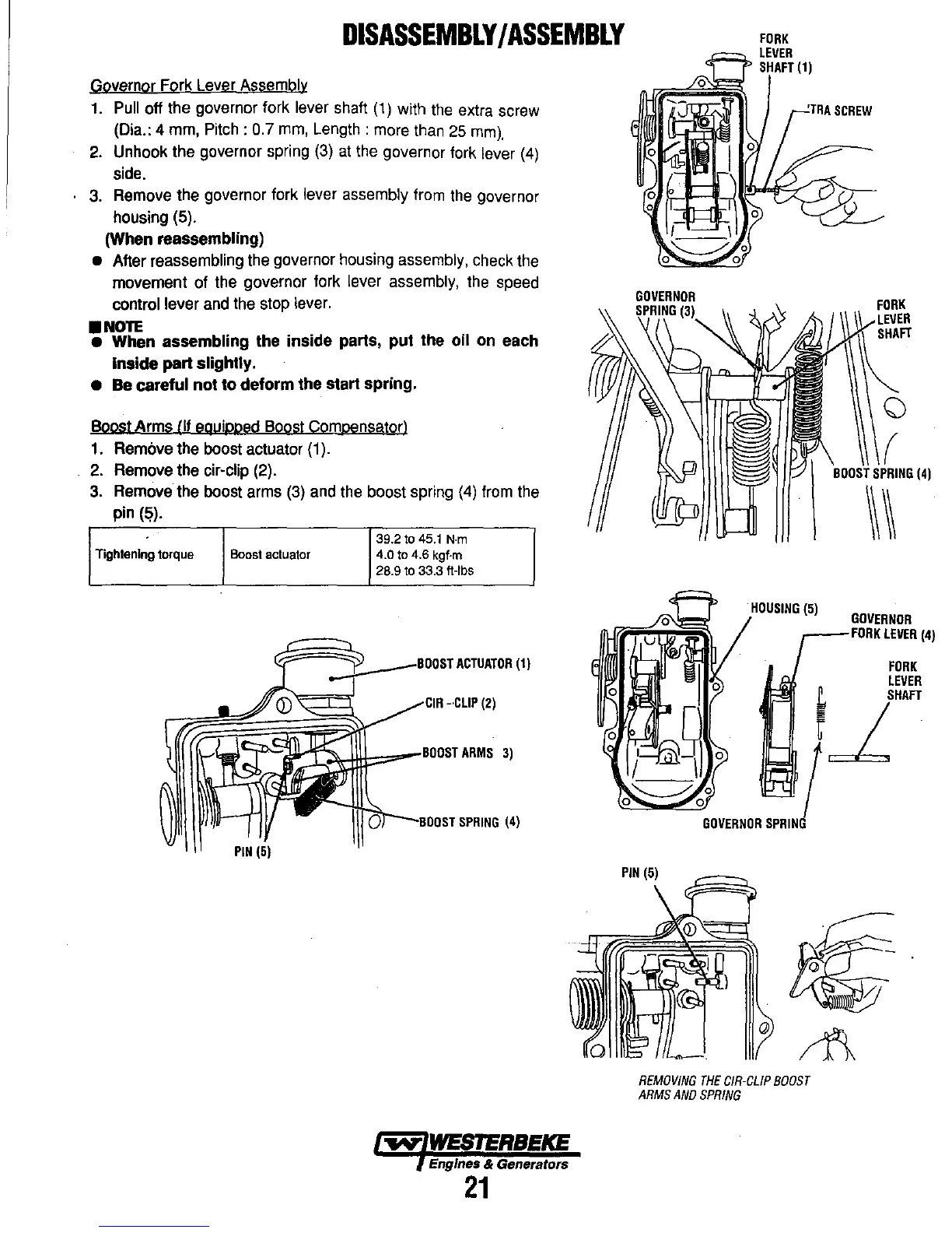
Governor Fork Lever Assembly
1. Pull off the governor fork lever shaft
(1)
with the extra screw
(Dia.: 4 mm,
Pitch:
0.7 mm, Length: more than 25
mm).
2.
Unhook the governor spring (3)
at
the governor fork lever (4)
side.
3. Remove the governor fork
lever assembly from the governor
housing (5).
(When reassembling)
• After reassembling the governor housing assembly, check the
movement
of
the governor fork lever assembly, the speed
control lever and the stop lever.
•
NOTE
• When assembling the inside parts, put the oil on each
Inside part slightly.
•
Be careful not
to
deform the start spring.
Boost
Arms
III equipped Boost Compensator)
1. Remove the boost actuator (1).
2. Remove the
cir-clip (2).
3. Remove the boost arms (3) and the boost spring (4) from the
pin
(fi).
39.2
to
45.1
N·m
Tightening
torque
Boost
actuator 4.0
to
4.6 kgf·m
28.9
to
33.3 ft-Ibs
."::J::-
__
IIOOiHACTUATOR
(1)
I ·,ClIP
(2)
'~~::r==a~f:~lli::=
__
BOIOST
ARMS
3)
nr--Rnln<T
SPRING
(4)
PIN
(5)
~
WESTERBEKE
Engines & Generators
21
GOVERNOR
PIN
(5)
()
(
(4)
\\~
HOUSING
(5)
GOVERNOR
,----FORK
LEVER
(4)
FORK
LEVER
t
SHAFT
r~
.
I
GOVERNOR
SPRING
REMOVING
THE
C/R-CLIP
BOOST
ARMS
AND
SPRING