TORQUE
SPECIFICATIONS
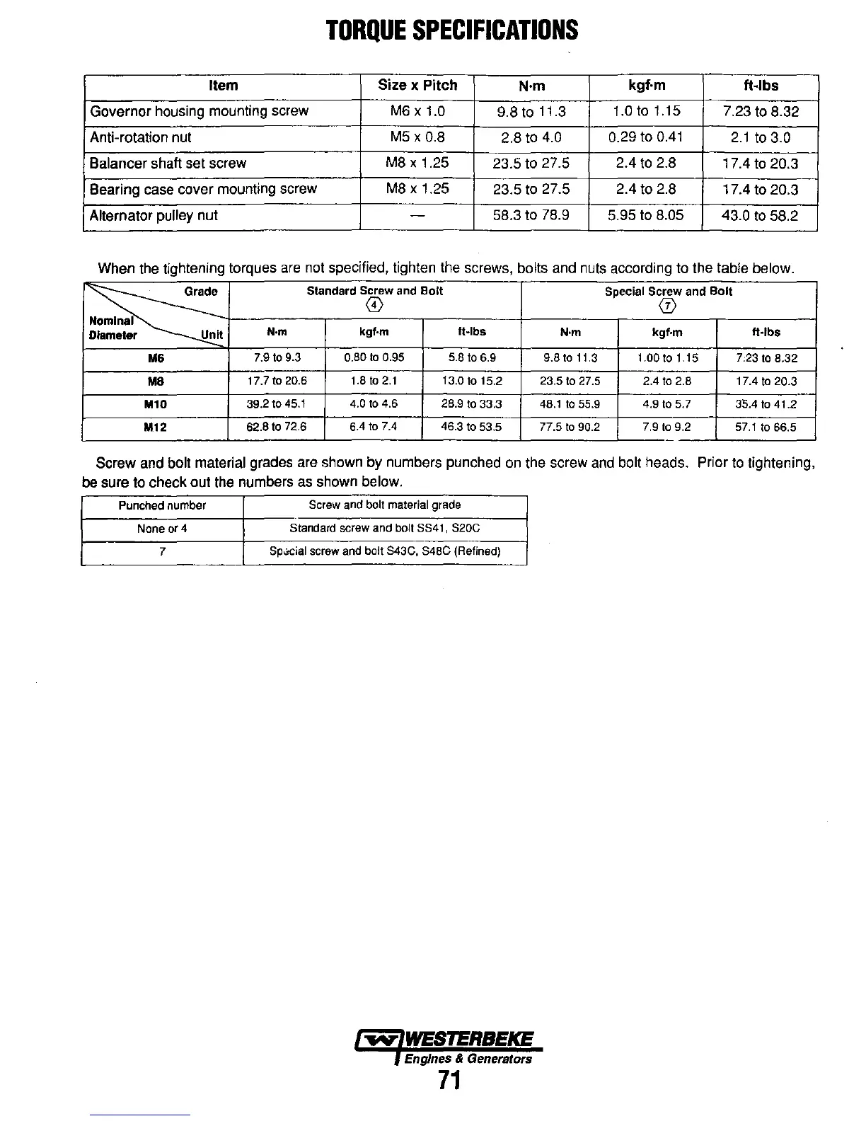
Item
Size
x Pitch
N·m
kgf·m
ft-lbs
Governor housing mounting screw M6 x 1.0
9.8 to 11.3
1.0t01.15
7.23 to 8.32
Anti-rotation nut
M5 x 0.8
2.8 to 4.0
0.29 to
0.41
2.1
to
3.0
Balancer shaft set screw
M8 x 1.25
23.5 to 27.5
2.4
to
2.8
17.4
to
20.3
Bearing case cover mounting screw
M8 x 1.25
23.5
to
27.5
2.4 to 2.8
17.4 to 20.3
Alternator pulley nut -
58.3 to 78.9
5.95 to 8.05 43.0
to
58.2
When the tightening torques
are
not specified, tighten the screws, bolts and nuts according to the table below.
!~e
Standard Screw
and
Bolt
Special Screw and Bolt
@
(j)
Nominal
Diameter
Unit
N·m
kgf·m
It·lbs
N·m kgf·m
It·lbs
M6
7.9
to
9.3 0.80
to
0.95 5.8
to
6.9
9.8
to
t t.3
t.OO
to
1.15 7,23
to
8.32
M8
t7.7
to
20.6
t.8
to
2.t
13.0
to
15.2 23.5
to
27.5
2.4
to
2.8 17.4
to
20.3
M10
39.2 to
45.1
4.0
to
4.6 28.9
to
33.3
48.11055.9 4.9
to
5.7 35.4
to
41.2
M12
62.8 to 72.6
6.4
to
7.4 46.3 to 53.5
77.5
to
90.2 7.9
to
9.2
57.1
to
66.5
Screw and bolt material grades are shown by numbers punched
on
the screw and bolt heads. Prior
to
tightening,
be sure
to
check out the numbers as shown below.
Punched
number
Screw
and
bolt
material
grade
None
or
4
Standard
screw
and
bolt
8841 , S20C
7
Sp.;cial screw and bolt S43C, S48C (Refined)
Engines
& Generators
71