en Product description
52 WILO SE 2019-07
4 Product description
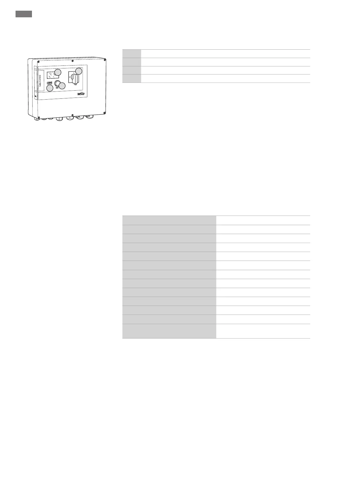
4.1 Structure
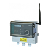
Fig.1: Switchgear front
1 Main switch
2 Operating button
3 LED indicators
4 LCD display
The front of the switchgear comprises the following main components:
▪Main switch for switching the switchgear on/off
▪Operating button for menu selection and parameter input
▪LEDs for displaying the current operating state
▪LCD display for showing the current operating data and individual menu items
4.2 How it works
The pumps are switched on/off individually and automatically depending on the actual
pressure in the system. The pressure control for the Control EC-Booster is carried out
using a two-point controller. The pressure control for the Control ECe-Booster is car-
ried out using a PID controller. When the dry running level is reached, a visual signal is
displayed and a forced switch-off of all the pumps occurs. Faults are stored in the fault
memory.
The current operating data and operating conditions are shown on the LCD display and
indicated by LEDs. Operation and the input of operating parameters is carried out using
a rotary knob.
4.3 Technical data
Date of manufacture*
See rating plate
Mains connection
See rating plate
Mains frequency
50/60Hz
Max. current consumption per pump
See type designation
Max. rated power per pump
See rating plate
Pump activation type
See type designation
Ambient/operating temperature
0 … 40°C
Storage temperature
-30 … +60°C
Max. relative humidity
90%, non-condensing
Protection class
IP54
Electrical safety
Pollution degree II
Control voltage
See rating plate
Housing material
UV-resistant polycarbonate or powder-
coated steel sheeting
*The date of manufacture is stated in accordance with ISO8601: JJJJWww
▪JJJJ = year
▪W = abbreviation for week
▪ww = calendar week
4.4 Inputs and outputs
Inputs
▪Analogue input:
– 1x passive pressure sensor 4–20mA
▪Digital inputs:
– 1x float switch/pressure switch used for sensing dry running level/low water level
– 1x Extern OFF: for remote switch-off of all pumps
▪Pump monitoring:
– Control EC-Booster: 1x input/pump for the thermal winding monitor using a bimetal-
lic strip
NOTICE!PTC and Pt100 sensors cannot be connected!
– Control ECe-Booster: 1x input/pump for frequency converter fault messages
 Loading...