Appendix en
Installation and operating instructions Wilo-Control EC/ECe-Booster 83
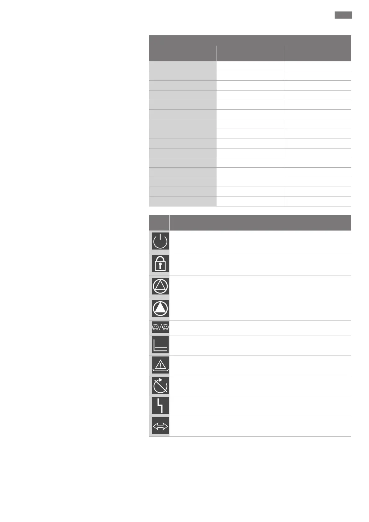
3~400V, 2-pole, direct starting
Power in kW System impedance in
ohms
Connections/h
2.2
0.321 6
2.2
0.257 12
2.2
0.212 18
2.2
0.186 24
2.2
0.167 30
3.0
0.204 6
3.0
0.148 12
3.0
0.122 18
3.0
0.107 24
4.0
0.130 6
4.0
0.094 12
4.0
0.077 18
5.5
0.115 6
5.5
0.083 12
5.5
0.069 18
13.2 Overview of the symbols
Sym-
bol
Description
Standby:
Symbol lights up: The switchgear is switched on and ready for operation.
Symbol flashing: Follow-up time of base-load pump is active
Value input not possible:
1. Input disabled
2. The accessed menu is a value display only.
Pumps ready for operation/deactivated:
Symbol lights up: Pump is available and ready for operation.
Symbol flashing: Pump is deactivated.
Pumps working/fault:
Symbol lights up: Pump is in operation.
Symbol flashing: Pump fault
A pump has been set as the standby pump.
Control mode: Constant pressure control (p-c)
Low-water monitoring /dry-running protection active
“Extern OFF” input active: All pumps switched off
There is at least one current (unacknowledged) error message.
The device communicates using a field bus system.
 Loading...