en Operation
64 WILO SE 2019-07
6.5.17 Connection ModBus RTU
NOTICE
Do not apply external voltage!
An external voltage which is applied destroys the component.
J4
J3
J2
J4
J2
J3
Control EC/ECe-B2 Control EC/ECe-B3
Fig.22: Jumper position
See Overview of components: Wilo-Control EC-Booster [}56] for position numbers
9 ModBus: RS485 interface
10 ModBus: Jumper for termination/polarisation
The ModBus protocol is available for connection to a building management system. In-
sert the connection cable laid by the customer through the threaded cable glands and
secure. Connect the wires to the terminal strip according to the connection diagram.
Observe the following points:
▪Interface: RS485
▪Field bus protocol settings: Menu 2.01 to 2.05.
▪The switchgear is terminated at the factory. Remove termination: Remove jumper “J2”.
▪If the ModBus requires a polarisation, plug in jumpers “J3” and “J4”.
7 Operation
DANGER
Risk of fatal injury due to electrical current!
Only operate the switchgear when closed. There is a risk of fatal injury from open
switchgear! Electrical work on the internal components must be carried out by a
qualified electrician.
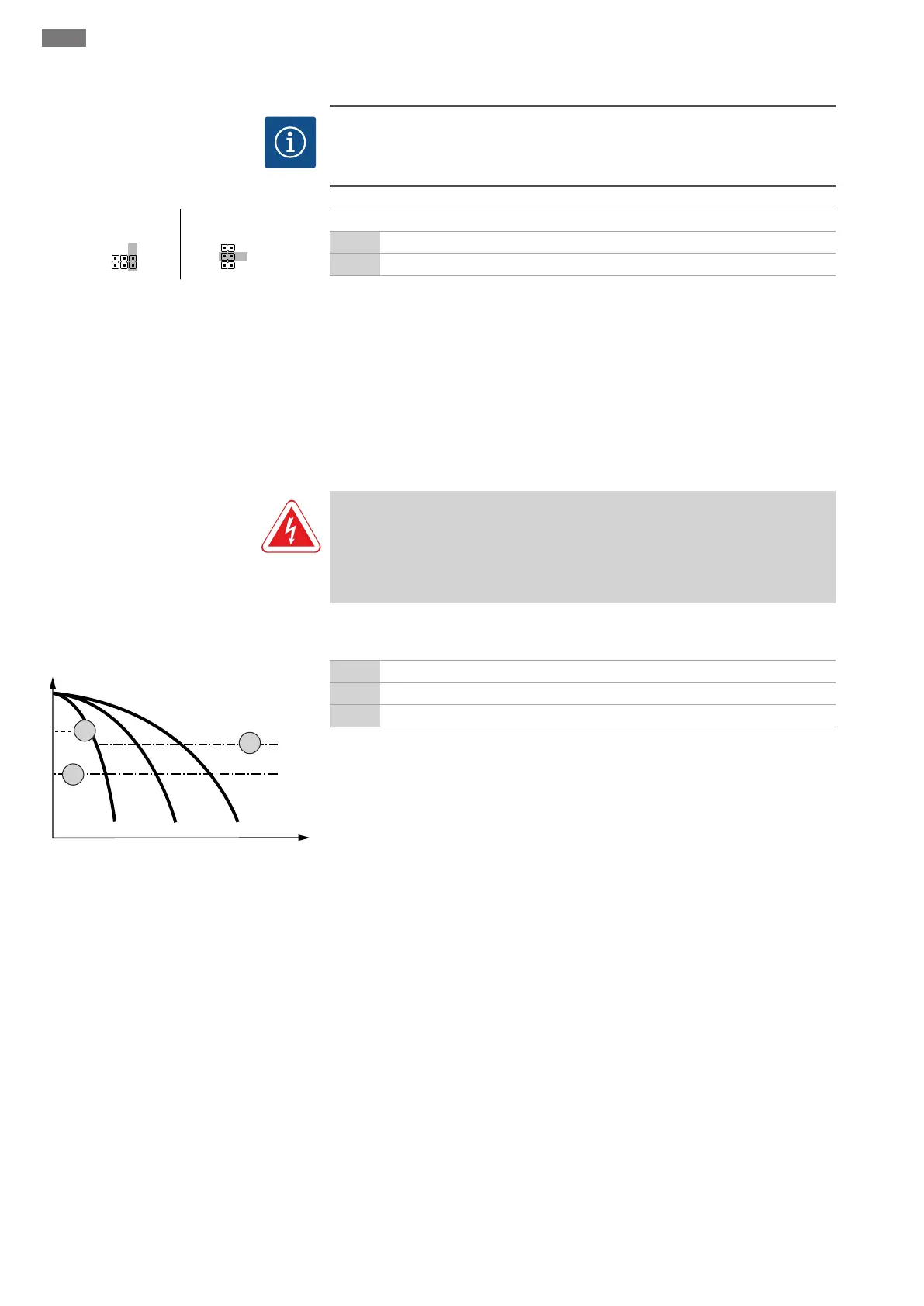
7.1 How it works
Wilo-Control EC-Booster
Fig.23: Functional diagram for Control EC-
Booster
2 Activation threshold
3 Deactivation threshold for base-load pump
4 Deactivation threshold for peak-load pumps
During normal operation, the system maintains a pressure in the range between the ac-
tivation and deactivation thresholds. Control is carried out as two-position control. A
pressure sensor measures the actual pressure value. If the pressure falls below the ac-
tivation threshold, the base-load pump switches on. Depending on the power require-
ment, the peak-load pumps are activated one by one. If the deactivation threshold for
the peak-load pumps is exceeded, the system turns off the peak-load pumps one by
one. If the deactivation threshold for the base-load pump is exceeded, the system turns
off the base-load pump. During operation, a visual indicator appears on the LCDdisplay
and the green LED lights up. To optimise pump running times, pump cycling is carried
out regularly.
In the event of a fault, the system automatically switches to a different pump. The error
code is shown on the LCD display and the red LED lights up. The outputs for the collect-
ive fault signal (SSM) and individual fault signal (ESM) are activated.
If the low water level in the break tank (dry-running protection) is reached, all pumps
are switched off. The error code is shown on the LCD display and the red LED lights up.
The output for the collective fault signal (SSM) is activated.
 Loading...