The ride height valves inflate or deflate the air bags keeping the
motorhome at proper suspension height throughout the load range. There are
three ride height control valves used on the motorhome. Two are used on the
rear drive axle, these control rear suspension height and left or right tilt of
the motorhome. Only one valve is used to control front axle suspension
height. The ride height control valves are mounted to the main frame of the
motorhome just above the axles. Each valve has a linkage rod connected the
axle. The valves make small air adjustments to the air springs while travel-
ing. Amount of system air used depends on the type of roadway surface and
driving styles.
Should it become necessary to check suspension ride height start with air
system fully charged and suspension at normal height. Motorhome must be
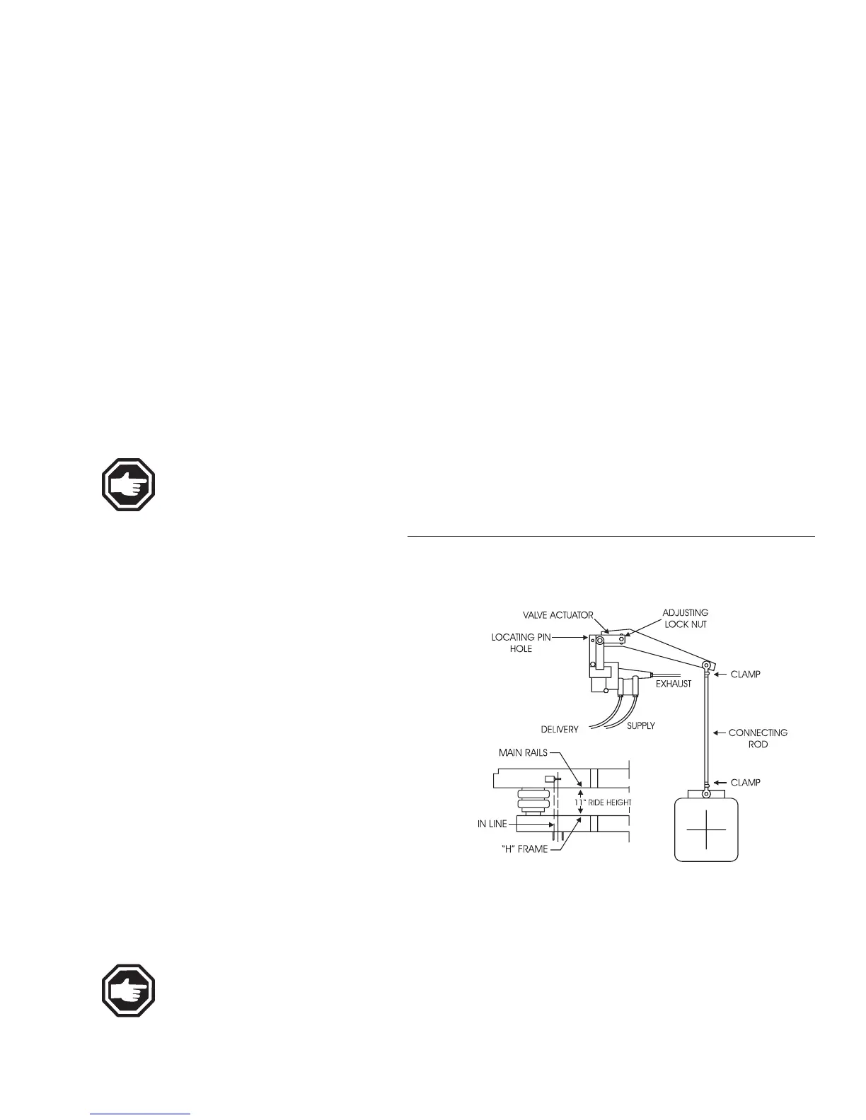
on a flat level surface. Suspension height distance is measured from the top
of the H-Frame to the bottom of the Main Frame Rail. Specified distances
may vary plus or minus 1/4”. Small adjustments to the rear valves may be
necessary to compensate for slight tilt. Example: Adjusting curbside rear
height control valve up will pivot roadside front corner down.
NOTE: Driveline angle is affected by the suspension ride
height. Improper driveline angle can damage suspension or
shorten life of universal joints. Shock absorbers and air springs
are in travel centers at proper ride height.
To adjust suspension ride height begin with:
• Motorhome on flat level surface.
• Air system fully charged.
• Suspension at normalized ride height.
Begin with front control valve. Loosen the
adjusting locknut at the eccentric slot on the valve.
Move the plastic arm up to raise suspension height,
this will inflate air springs. Move the plastic arm
down to lower suspension height, this will deflate
air springs. Make small increment adjustments.
When desired height is obtained insert a 1/8” or
7/64” inch twist drill bit into the plastic arm and
valve body. This will central travel of internal pis-
ton. Tighten adjusting locknut between 60-80 in/lbs.
Check adjustments made by using Air Dump switch
to deflate air springs. Start engine to allow air
system to become fully charged. Allow suspension
to adjust and come to a neutral setting. Re-check
suspension height measurement. Follow same pro-
cedure for rear control valves. Re-check the front
suspension height when adjustments are made to
rear height control valves.
NOTE: Do not modify length of the linkage rods. Make neces-
sary adjustments using eccentric slot on ride height control
valve.
Chassis Information
------------------------------------------------------------------------------------------------------------------------------------------------------------------------------------------------------------------------------------------------------------------------------------------------------------------
WINDSOR
10•263
RIDE HEIGHT
VALVES
Adjusting
Checking Ride Height
Measurement for the Windsor:
Front = 9 ½ in., Rear = 11 in.