Manual 37278B GCP-30 Series - Genset Control
Page 152/174 © Woodward
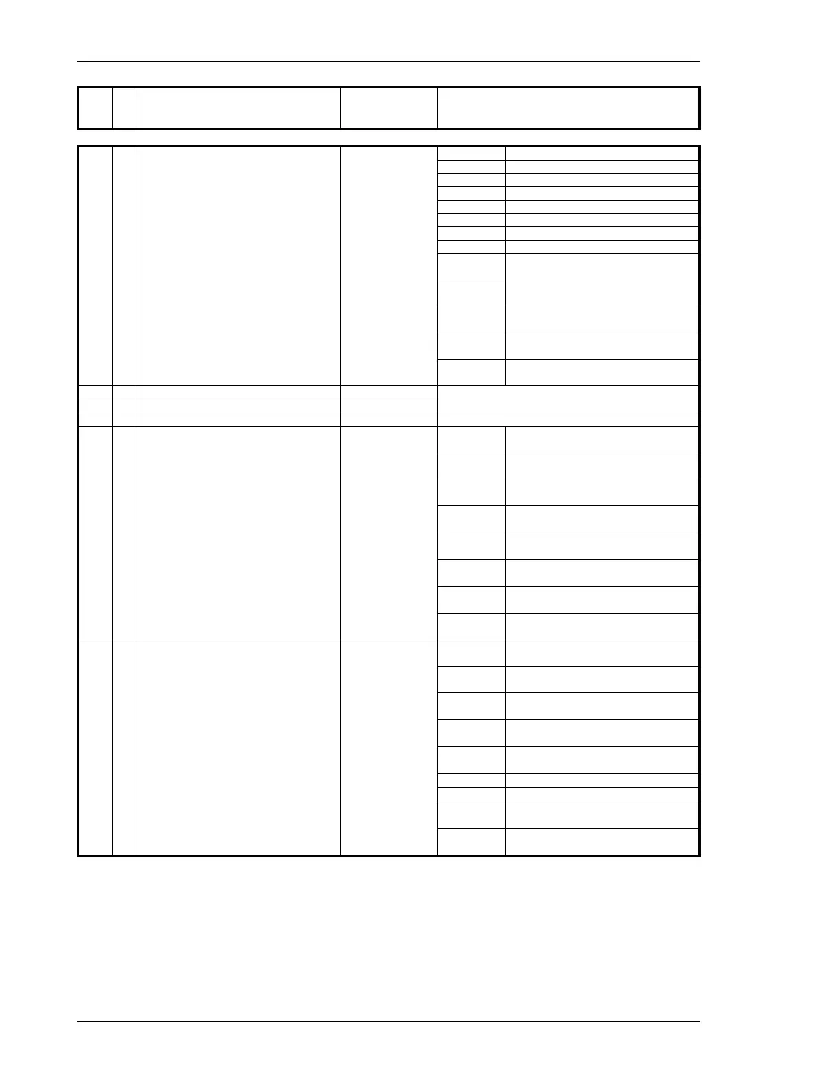
MUX
No.
Contents (words)
Unit Note
16/1 49
Operation mode Bit 15 = 1 LOAD TEST operation mode
Note – On double /fourfold bits the follow-
ing is valid: If the indicated bit combination
is fulfilled (
high byte and low byte) ,the
message is active (otherwise inactive).
Bit 14 = 1 STOP operation mode
Bit 13 = 1 TEST operation mode
Bit 12 = 1 MANUAL operation mode
Bit 11 = 1 AUTOMATIC operation mode
Bit 10 = 1 --Internal--
Bit 9 = 1 --Internal--
Bit 8 = 1 --Internal--
Bit 7 = 1
Bit 6 = 0
Emergency power is ON
Bit 7 = 0
Bit 6 = 1
Emergency power is OFF
Bit 5 = 1
Bit 4 = 1
Delayed engine monitoring is ON
Bit 3 = 1
Bit 2 = 1
Cool down expired
Bit 1 = 1
Bit 0 = 1
--Internal--
16/2 50
Generator active energy ( H.W.)
kWh × 2
16
Double word
16/3 51
Generator active energy (L.W.)
kWh
17/1 52
Battery voltage V × 10
17/2 53
Internal alarm 1
Bit 15 = 1 \
Bit 14 = 1 /
F3: Generator overfrequency 1
Note – On double /fourfold bits the follow-
ing is valid: If the indicated bit combination
is fulfilled (
high byte and low byte) ,the
message is active (otherwise inactive).
Bit 13 = 1 \
Bit 12 = 1 /
F3: Generator underfrequency 1
Bit 11 = 1 \
Bit 10 = 1 /
F3: Generator overvoltage 1
Bit 9 = 1 \
Bit 8 = 1 /
F3: Generator undervoltage 1
Bit 7 = 1 \
Bit 6 = 1 /
--Internal--
Bit 5 = 1 \
Bit 4 = 1 /
F1: Battery undervoltage
Bit 3 = 1 \
Bit 2 = 1 /
F3: Generator overload
Bit 1 = 1 \
Bit 0 = 1 /
F3: Generator reverse power
17/3 54
Internal alarm 2
Bit 15 = 1 \
Bit 14 = 1 /
F0: Mains overfrequency
Note – On double /fourfold bits the follow-
ing is valid: If the indicated bit combination
is fulfilled (
high byte and low byte) ,the
message is active (otherwise inactive).
Bit 13 = 1 \
Bit 12 = 1 /
F0: Mains underfrequency
Bit 11 = 1 \
Bit 10 = 1 /
F0: Mains overvoltage
Bit 9 = 1 \
Bit 8 = 1 /
F0: Mains undervoltage
Bit 7 = 1 \
Bit 6 = 1 /
Interface fault X1-X5
Bit 5 = 1 GCB opened; "Time ad-on ramp" expired
Bit 4 = 1 --Internal--
Bit 3 = 1 \
Bit 2 = 1 /
--Internal--
Bit 1 = 1 \
Bit 0 = 1 /
F0: Mains phase/vector jump

 Loading...


