Introduction
M370046-01 4-7
4
Making Control Connections
To connect the output wires to the APG and DC output connector:
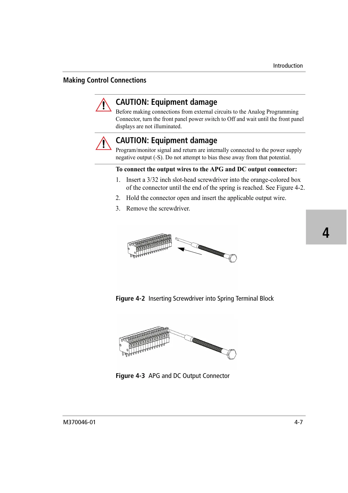
1. Insert a 3/32 inch slot-head screwdriver into the orange-colored box
of the connector until the end of the spring is reached. See Figure 4-2.
2. Hold the connector open and insert the applicable output wire.
3. Remove the screwdriver.
CAUTION: Equipment damage
Before making connections from external circuits to the Analog Programming
Connector, turn the front panel power switch to Off and wait until the front panel
displays are not illuminated.
CAUTION: Equipment damage
Program/monitor signal and return are internally connected to the power supply
negative output (-S). Do not attempt to bias these away from that potential.
Figure 4-2
Inserting Screwdriver into Spring Terminal Block
Figure 4-3
APG and DC Output Connector

 Loading...