Do you have a question about the Xerox 7142 and is the answer not in the manual?
Explains the manual's purpose, target audience, and structure for effective use.
Details the sections included in the manual for user guidance and understanding.
Explains safety terms, important instructions, and warning labels for safe operation.
Categorizes safety terms by risk level to ensure user comprehension and adherence.
Provides general safety guidelines that must be observed for the safe use of the equipment.
Details the handling, attachment locations, and types of warning labels on the equipment.
Describes operation labels, their types, and positions for brief instructions on key operations.
Introduces the chapter covering the plotter's features, part names, and functions.
Explains the plotter's key features, including image quality, ink system, and operability improvements.
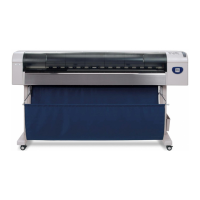
Identifies and describes the plotter's various parts and their specific functions.
Explains the different operational statuses of the plotter, such as Normal and Setup Menu.
Introduces specifications, optional parts, supplies, and installation environment requirements.
Details main unit and plot operation specifications like dimensions, accuracy, and media handling.
Describes the USB and Network interface specifications supported by the plotter.
Lists available optional accessories and consumable supplies for the plotter.
Provides installation environment requirements and guidance on selecting a suitable location.
Provides essential information and warnings regarding the removal and replacement of service parts.
Details the procedure for removing external covers to access internal components for service.
Explains replacement procedures for board assemblies, NIC, and cooling fan.
Details procedures for replacing components within the PF driving section, such as motors.
Outlines procedures for replacing components in the CR driving section, including motors and belts.
Provides procedures for replacing components within the head section, including the print head.
Describes procedures for replacing components located in the maintenance section.
Details procedures for replacing components within the ink supply section, such as ink holders.
Outlines procedures for replacing components within the frame section, such as suction fans.
Describes procedures for replacing components within the cable guide section, such as CR board.
Introduces the self-diagnosis function for accuracy adjustment and checking part conditions.
Details necessary preparations, including media setting and power connection, before self-diagnosis.
Explains how to operate the self-diagnosis mode and lists available diagnosis items.
Lists diagnostic items for checking circuit boards, sensors, and fans.
Covers menu items for aligning printing position and correcting media feed operation.
Performs endurance running tests on mechanical parts and the head for durability checks.
Introduces maintenance mode for displaying and initializing life counters.
Explains how to start up and operate maintenance mode2, listing available diagnostic items.
Lists diagnostic items within the maintenance menu, focusing on counter display and initialization.
Provides information on necessary adjustment items and procedures for optimal performance.
Describes adjustment items required after part replacement procedures and their references.
Explains parameter backup, firmware installation, and sending parameters using network software.
Details the procedure for adjusting the PF speed reduction belt tension using specific jigs.
Outlines the procedure to adjust the PF encoder assembly position using measurement tools.
Describes the procedure to adjust the tension of the CR belt for proper operation.
Explains how to adjust the head slant in the horizontal direction based on test patterns.
Details the procedure to adjust the head slant in the vertical direction using adjustment tabs.
Covers the procedure for adjusting the cutter holder height using specialized jigs.
Describes the procedure to check and adjust the carriage height from the platen.
Explains how to adjust the sensitivity of the P_EDGE and P_REAR media sensors.
Provides information on periodical services, part life, lubrication, bonding, and transport.
Describes periodical services required to ensure stable plotting quality and lists inspection items.
Shows how to check the life of service parts using maintenance counters and their references.
Covers lubrication and bonding information required after disassembly/assembly procedures.
Provides instructions on how to properly package and transport the plotter to prevent damage.
Provides information on possible causes of errors, damage, and recovery actions.
Describes messages displayed during operation and errors, with check items and recovery actions.
Details symptoms of errors without messages, including check items and recovery actions.
Provides referential information such as service data and exploded views.
Provides information for accessing the wiring diagram for service reference.
Lists maintenance parts required for service operations and their references.
Lists jigs and tools required for service operations, including part replacement and adjustment.