October 2012
7-3
ColorQube 8570/8870 Service Manual
How to Use the Plug/ Jack Location List
Wiring Data
Xerox Internal Use Only - Revised, 3rd Revision
How to Use the Plug/ Jack Location List
The P/J Locator diagrams show the location of primary connections within the printer. Use
these illustrations to locate connections called out in the procedures presented in Sections 2,
4, and 6. Connectors designated “CN” are listed at the end of the P/J connectors.
To find the location of a Plug or Jack:
1. Locate the P/J connector designator in the first column of the table.
2. With this information, go to the second column (Map - Figure Number).
3. Use the coordinates to locate the connection indicated on the map with its P/J designation
number. If coordinates are not given, go to the referenced Wire Routing Diagrams.
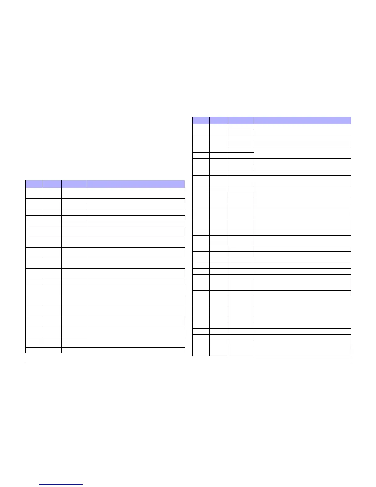
Table 1 Plug/ Jack Location
P/J Map Coordinates Remarks
P/J1 Figure 12 F-108 Connects the Ink Loader Thermistor to the Ink Loader
Board.
P/J101 Figure 2 E-105 Printer Serial Debug Port
P/J101 Figure 5 B-107 Connects the I/O Board to the Outer Duplex Guide.
P/J101 Figure 11 G-108 Connects the Ink Loader Board to the Ink Loader Sensor.
P/J102 Figure 5 B-107 Connects the I/O Board to the Waste Tray Detect Sensor.
P/J110 Figure 6 G-108 Test connection (not used in printer).
P/J115 Figure 1 D107 Connects the Paper Preheater to the Front Side Har-
ness.
P/J125 Figure 1 D-107 Connects the Preheater Temperature Thermistor, Pre-
heat Sensor, and Deskew Entry Sensor to the I/O Board.
P/J126 Figure 1 D-107 Connects the Tray 2 Paper Height Sensor to the Right
Side Harness.
P/J127 Figure 1 C-107 Connects the No Paper Sensor to the Right Side Har-
ness.
P/J129 Figure 1 F-108 Connects the Tray 1 Width Sensor/ No Paper Sensor to
the I/O Board.
P/J130 Figure 6 F-107 Connects the Printhead Board to the Level Sense.
P/J130 Figure 13 H-107 Connects the Drum Temperature Sensor to the Right
Side Harness.
P/J131 Figure 14 F-108 Connects the Paper Size Sensor to the Right Side Har-
ness.
P/J180 Figure 6 C-107 Connects the Printhead to the Main Controller Board
(Electronics Module).
P/J190 Figure 6 B-105 Connects the Printhead Board to the Printhead Reservoir
Thermal.
P/J201 Figure 4 G-105 Connects the Power Supply (Electronics Module) to the
Printhead.
P/J201 Figure 8 D-103 Connects the Main Controller Board to the Printhead
Board.
P/J240 Figure 6 E-106 Connects the Printhead Heater to the Wave Amp.
P/J301 Figure 3 H-110 Connects the Power Control Board (Electronics Module)
to the Y-Axis Motor.
P/J301 Figure 9 I-135
P/J301 Figure 5 G-104 No connection on the I/O Board.
P/J301 Figure 11 A-137 Connects the Ink Loader Board to the Ink Loader Sensor.
P/J302 Figure 3 F-109 Connects the Power Control Board (Electronics Module)
to the Left Side Harness.
P/J302 Figure 9 I-135
P/J401 Figure 2 D-109 Connects the Power Control Board (Electronics Module)
to the Ink Loader Board.
P/J401 Figure 9 A-136
P/J401 Figure 8 A-106 USB Connection.
P/J401 Figure 5 C-107 Connects the I/O Board to the Preheater and Tray 2 Sen-
sors.
P/J402 Figure 2 C-109 Connects the Power Control Board (Electronics Module)
to the I/O Board.
P/J402 Figure 9 A-135
P/J402 Figure 5 B-108 Connects the I/O Board to the Tray 1 (MPT).
P/J403 Figure 5 E-104 Connects the I/O Board to the Control Panel.
P/J403 Figure 9 C-136 Connects the Power Control Board (Electronics Module)
to the Main Controller Board.
P/J505 Figure 8 G-106 Connects the Main Controller Board to the Hard Disk
Drive.
P/J601 Figure 5 H-105 Connects the I/O Board to the Exit Module.
P/J601 Figure 9 G-135 Connects the Power Control Board to the Power Supply
(Electronics Module).
P/J640 Figure 7 E-106 Connects the Wave Amplifier to the Printhead Heater.
P/J701 Figure 2 F-109 Connects the Power Control Board (Electronics Module)
to the I/O Board.
P/J701 Figure 9 A-136
P/J701 Figure 5 C-108 Connects the I/O Board to the Paper Size Sensor.
P/J701 Figure 11 J-136 Connects the Ink Loader Board to the Solenoid.
P/J702 Figure 5 D-108 Connects the I/O Board to the Predeskew Sensor.
P/J702 Figure 11 I-136 Connects the Ink Loader Board to the Power Control
Board (Electronics Module).
P/J703 Figure 11 H-105 Connects the Ink Loader Board to the Thermistor.
P/J800 Figure 7 A-107 Connects the Wave Amplifier to the Power Control Board
(Electronics Module).
P/J801 Figure 5 F-107 Connects the I/O Board to the Power Control Board
(Electronics Module).
P/J801 Figure 11 G-105 Connects the Ink Loader Board to the Solenoid.
P/J802 Figure 11 C-105 Connects the Ink Loader Board to the Solenoid.
P/J803 Figure 8 F-109 Connects the Main Controller Board to the Hard Drive.
P/J901 Figure 3 D-109 Connects the Power Control Board (Electronics Module)
to the Wave Amplifier.
P/J901 Figure 9 I-137
P/J901 Figure 5 G-106 Connects the I/O Board to the Drum Maintenance Pivot
Plate.
Table 1 Plug/ Jack Location
P/J Map Coordinates Remarks

 Loading...