October 2012
7-4
ColorQube 8570/8870 Service Manual
How to Use the Plug/ Jack Location List, Plug/Jack
Revised, 3rd Revision - Xerox Internal Use Only
Wiring Data
Plug/Jack Locations
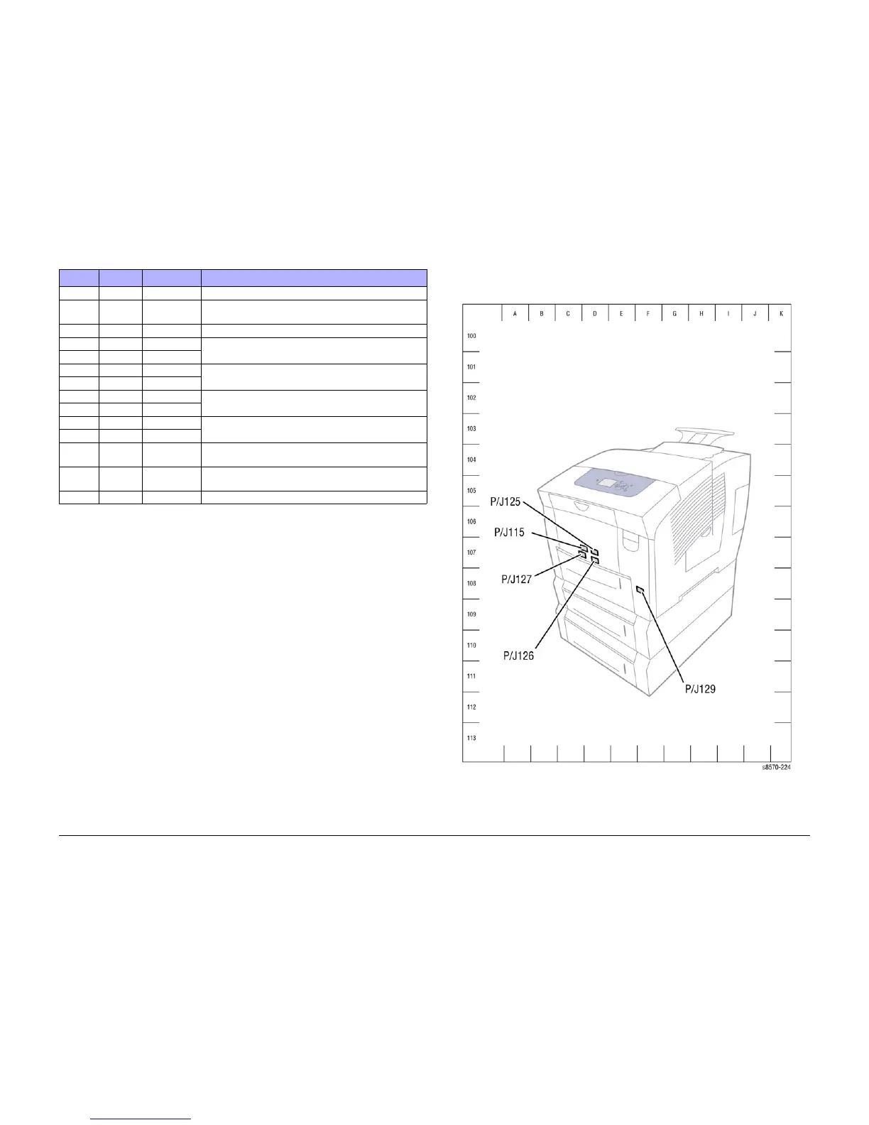
Front Side
Figure 1 Front Side P/J Locations
P/J901 Figure 11 A-135 Connects the Ink Loader Board to the Solenoid.
P/J902 Figure 5 H-107 Connects the I/O Board to the Drum Temperature Sen-
sor.
P/J903 Figure 5 H-106 Connects the I/O Board to the Drum Fan.
P/JAC1 Figure 4 E-106 Connects the printer Power Supply (Electronics Module)
to the Ink Melt Heaters.
P/JAC1 Figure 10 E-104
P/JAC2 Figure 4 H-106 Connects the printer Power Supply (Electronics Module)
to the Printhead Heaters.
P/JAC2 Figure 10 H-104
P/JAC3 Figure 2 D-104 Connects the printer Power Supply (Electronics Module)
to the Preheater.
P/JAC3 Figure 10 J-103
AC Inlet Figure 2 D-107 Connects the AC Line to the printer Power Supply (Elec-
tronics Module).
AC Inlet Figure 10 I-107
Ether-
net
Figure 2 E-108 Printer Ethernet LAN Port
JDC1 Figure 10 C-110 Connects the Power Supply Board to the Power Control
Board.
USB Figure 2 E-107 Printer USB Port
Table 1 Plug/ Jack Location
P/J Map Coordinates Remarks

 Loading...