KCU116 Board User Guide 13
UG1239 (v1.2) September 28, 2018 www.xilinx.com
Chapter2: Board Setup and Configuration
Jumpers
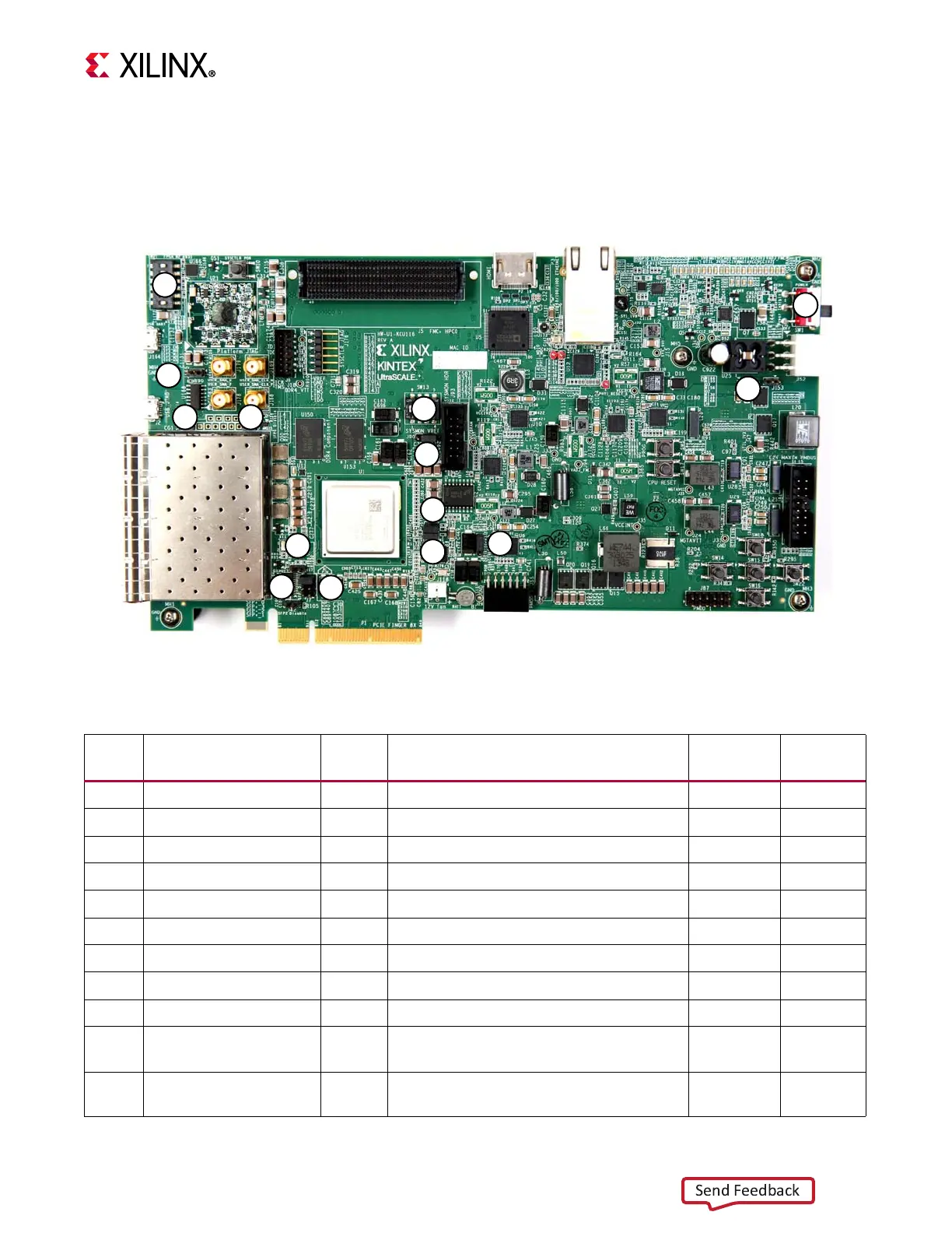
Figure 2-2 shows the KCU116 board jumper header locations. Each numbered component
shown in the figure is keyed to Table 2-3, which identifies the default jumper settings and
references the respective schematic page numbers.
X-Ref Target - Figure 2-2
Figure2‐2: KCU116 Board Header Jumper Locations
9
4
8
5
6
11
12
2
710
14
3
13
1
X18420-120916
Table2‐3: Default Jumper Settings
Jumper Function Default Comments
Figure 2‐2
Callout
Schematic
Page
J7 PCIe lane size select 5-6 8-lane configuration 4 20
J12 SYSMON_VP 1-2 U1 VP pin P13 pull down 20.5K to GND 5 3
J13 SYSMON_VN 1-2 U1 VN pin R14 pull down 20.5K to GND 6 3
J16 zSFP0 TX enable Off Disable zSFP0 TX, allow FPGA control 7 26
J17 zSFP1 TX enable Off Disable zSFP1 TX, allow FPGA control 8 26
J42 zSFP2 TX enable Off Disable zSFP2 TX, allow FPGA control 9 27
J54 zSFP3 TX enable Off Disable zSFP3 TX, allow FPGA control 10 27
J85 POR override 2-3 U1 POR_OVERRIDE pin Y12 to GND 11 3
J90 SYSMON_VREFP select 1-2 SYSMON_VREFP = U64 1.25V VREF 12 3
J153 Maxim regulator inhibit Off
Used only when programming power
system
13 44
J165 System controller boot Off
On = force Zynq-7000 AP SoC to boot in
JTAG mode on power-up or reset
14 32