KCU116 Board User Guide 65
UG1239 (v1.2) September 28, 2018 www.xilinx.com
Chapter3: Board Component Descriptions
Table 3-21 shows the level shifter U41 and U42 connections to FPGA U1
For more information about Pmod connector compatible Pmod modules, see the Digilent
website [Ref 26].
Switches
[Figure 2-1, callouts 27, 31]
The KCU116 evaluation board includes a power on/off slide switch and a configuration
pushbutton switch:
• Power on/off slide switch SW1 (callout 31)
• FPGA PROG_B SW4, active-Low (callout 27)
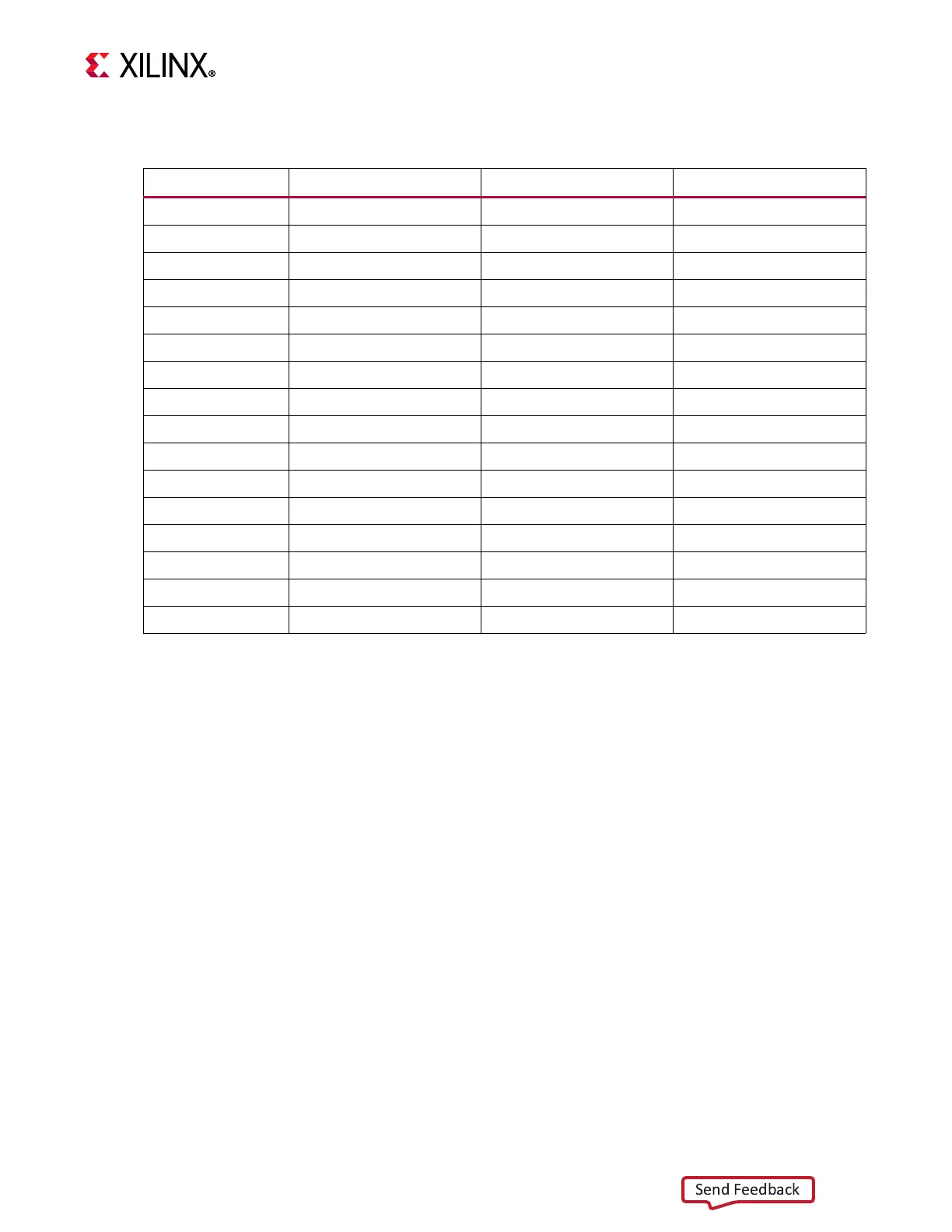
Table3‐21: Pmod Connector J55, J87 Connections to FPGA U1
FPGA (U1) Pin Schematic Net Name I/O Standard PMOD Conn. Pin
A14 PMOD0_0 LVCMOS33 J55.1
B14 PMOD0_1 LVCMOS33 J55.3
A12 PMOD0_2 LVCMOS33 J55.5
A13 PMOD0_3 LVCMOS33 J55.7
B12 PMOD0_4 LVCMOS33 J55.2
C12 PMOD0_5 LVCMOS33 J55.4
C13 PMOD0_6 LVCMOS33 J55.6
C14 PMOD0_7 LVCMOS33 J55.8
D13 PMOD1_0 LVCMOS33 J87.1
D14 PMOD1_1 LVCMOS33 J87.3
E12 PMOD1_2 LVCMOS33 J87.5
E13 PMOD1_3 LVCMOS33 J87.7
F13 PMOD1_4 LVCMOS33 J87.2
F14 PMOD1_5 LVCMOS33 J87.4
J14 PMOD1_6 LVCMOS33 J87.6
J15 PMOD1_7 LVCMOS33 J87.8