KCU116 Board User Guide 12
UG1239 (v1.2) September 28, 2018 www.xilinx.com
Chapter2: Board Setup and Configuration
Default Switch and Jumper Settings
Switches
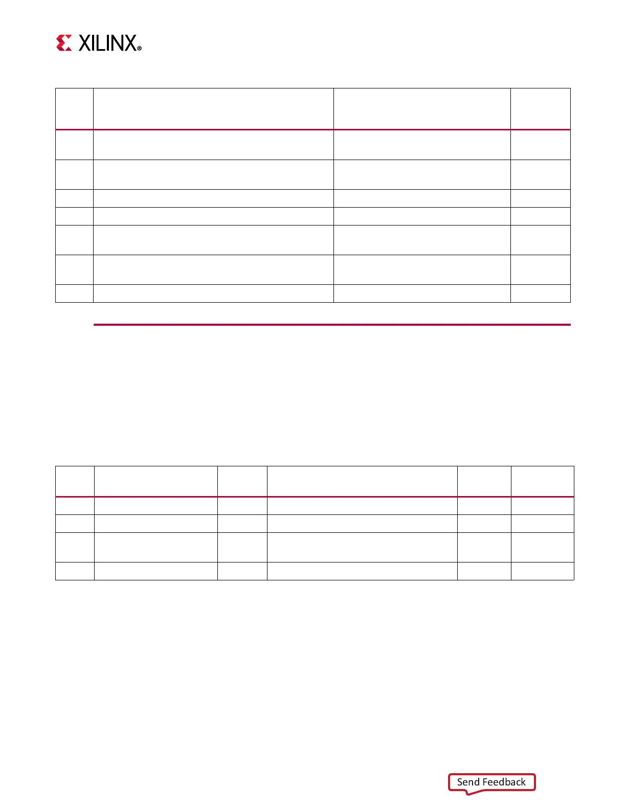
Default switch settings are listed in Table 2-2. Switch locations are shown in Figure 2-1.
Table 2-2 also references the respective schematic page numbers.
32
Monitoring Voltage and Current, 2x8 shrouded
PMBus connector (J84)
ASSMAN AWHW16G-0202 43
33
KCU116 Board Power System, power management
system (top and bottom)
Maxim MAX15301, MAX15303 and
MAX20751 Digital P.O.L. controllers
44-58
34 FMC HPC Connector J5 Samtec ASP_134486_01 21-24
35 SYSMON Header J93, 2X6 shrouded (J93) Molex 70246-1201 4
36
System Controller
Zynq
®
-7000 AP SoC XC7Z010CLG225 (U161)
XC7Z010CLG225 on bottom of board 31-34
37
USB JTAG Interface, 2x7 2 mm shrouded JTAG cable
connector (J8)
Molex 87832-1420 17
38 Encryption Key Battery Backup Circuit (B1) Seiko TS518FE-FL35E 3
Table2‐1: KCU116 Board Component Descriptions (Cont’d)
Callout Feature Notes
Schematic
Page
Number
Table2‐2: Default Switch Settings
Switch Function Default Comments
Figure 2‐1
Callout
Schematic
Page
SW1 SPST slide switch OFF Board shipped with power switch off 1 44
SW13 4-pole GPIO DIP 0,0,0,0 Positions 1-4, GPIO 2 40
SW21 6-pole configuration DIP 0,0,0,0,0
Positions 1-5, Zynq-7000 AP SoC System
Controller U161
334
SW21 6-pole configuration DIP 0 Position 6 FPGA U1 mode M2 3 34
Notes:
1. DIP switches are active-High (connected net is pulled High when DIP switch is closed=1).