KCU116 Board User Guide 48
UG1239 (v1.2) September 28, 2018 www.xilinx.com
Chapter3: Board Component Descriptions
Ethernet PHY Status LEDs
[Figure 2-1, callout 17]
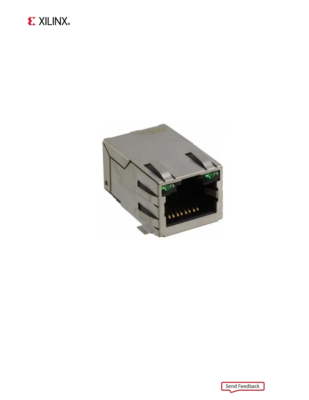
The TI DP83867ISRGZ PHY U12 LED interface (LED_0, LED_2) uses the two status LEDs
integrated into the metal frame of the P3 RJ-45 connector. These LEDs are visible on the left
edge of the KCU116 board when it is installed into a PCIe slot in a PC chassis. The two PHY
status LEDs are visible within the frame of the RJ-45 Ethernet jack as shown in Figure 3-16.
As viewed from the front opening, the left green LED is the link activity indicator and the
right green LED is the 1000BASE-T link mode indicator.
A separate discrete LED on top of the board (DS11, near U12) indicates link established.
The LED functions can be re-purposed with a LEDCR1 register write. LED_2 is assigned to
ACT (activity indicator) and LED_0 indicates link established. For more Ethernet PHY details,
see the TI DS83867 data sheet [Ref 31]. Details about the tri-mode Ethernet MAC core are
provided in Tri-Mode Ethernet MAC LogiCORE IP Product Guide (PG051) [Ref 10].
X-Ref Target - Figure 3-16
Figure3‐16: KCU116 Ethernet PHY Status LEDs