KCU116 Board User Guide 42
UG1239 (v1.2) September 28, 2018 www.xilinx.com
Chapter3: Board Component Descriptions
zSFP/zSFP+ Module Connectors
[Figure 2-1, callouts 14, 15]
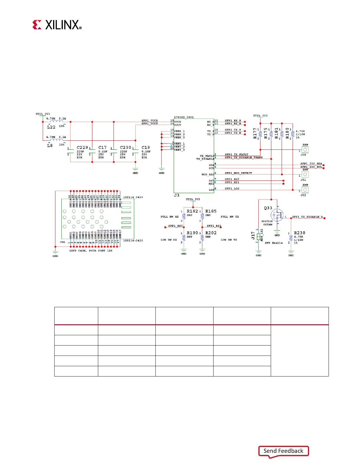
The KCU116 board hosts four zSFP/zSFP+ J1, J3, J4, and J6 that accept zSFP or zSFP+
modules. The connectors are housed within a single quad zSFP cage assembly. Figure 3-14
shows the zSFP/zSFP+ module connector circuitry typical of the four implementations.
Table 3-10 lists the zSFP+ module connections to FPGA U1.
X-Ref Target - Figure 3-14
Figure3‐14: zSFP/zSFP+ Module Connector
Table3‐10: KCU116 FPGA U1 to zSFP0‐zSFP3 Module Connections
FPGA (U1) Pin
Schematic Net
Name
Pin Number Pin Name SFP/SFP+ Module
M2 SFP0_RX_P 13 RD_P
zSFP0 J1
M1 SFP0_RX_N 12 RD_N
N5 SFP0_TX_P 18 TD_P
N4 SFP0_TX_N 19 TD_N
AB14 SFP0_TX_DISABLE_B 3 TX_DISABLE