PREMIUM E-MOBILITY
YD-EM279
26
18 1
17 2
16 3
15 4
14 5
13 6
12 7
11 8
10 9
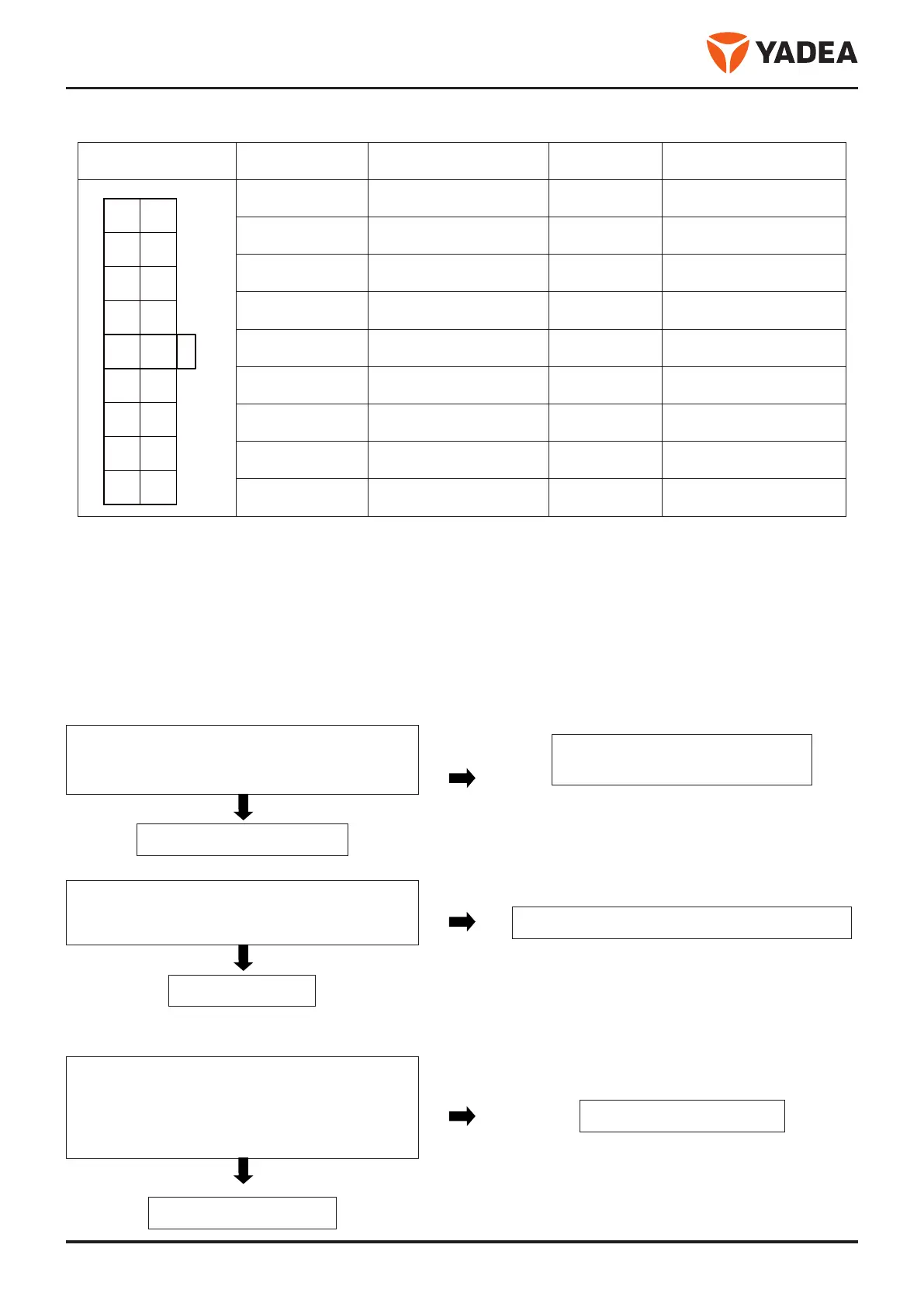
3.2.5.3 Connector interface definition
Interface style (black)
Pin
Function
Pin
Function
1 CAN + 10 CAN -
2 Right turn signal 11 Candlestick
3 Left turn signal 12 12V input
4 12V output 13 PUSH picks up the key
5 Solenoid valve output 14 Lock the motor signal
6 NC 15 Knob lock breathing light
7 ACC2 16 Knob lock key light
8 ACC1 17 Rotational signal
9 Power supply VCC 18 地 GND
3.2.5.4 Burglar alarm fault maintenance determination method
Function definition: know the vehicle status timely in case of vehicle and people separation by using the signal trans-
mission between the electric vehicle power supply and remote control to make burglar alarm and take corresponding
measures for anti - theft.
Common faults: no effect of remote control, unable to unlock, sensitive and insensitive anti - theft
Fault phenomenon: no effect of remote control, i.e. no response when the remote control is used to dis-
arm.
(1) Check the remote control battery:
Remote control battery: press the button to ob-
serve the LED indicator of the remote control
No
indication
1. Change the spare remote control.
2. Replace the internal button cell.
With indication
Judge remote control normal
(2) Burglar alarm input voltage check:
Use the DC gear of the multimeter to measure
whether the voltage input at the input end of the
power supply is 70V.
No voltage
Check the battery voltage and power input loop.
With voltage
Judge input normal
Fault phenomenon: unable to unlock, i.e. unable to disarm when the remote control is used to disarm.
(1) Remote control pairing code lost:
The anti-theft device turns the ACC-OFF to ACC-
ON five times in the decommissioned state, enters
the code mode, presses the remote control handle
within 20s, enters the learning state, and does not
find the key in the 20s, the code time-out exits.
Abnormal
Rematch the remote control
Normal
Check the remote control

 Loading...