YD-EM279
35
PREMIUM E-MOBILITY
3.2.13.3 Connector interface definition
Connector
Left combination switch Right combination switch
No
Interface
definition
Color No
Interface
definition
Color
1 Flasher Gray/QVR 0.3 1 P Yellow white/qvr 0.3
2 Horn Purple/QVR 0.5 2
Turnbar power
+
Red white/qvr 0.3
3 Gnd Green /QVR 0.5 3 Gnd Green/qvr 0.3
4 Turn left Orange/qvr 0.3 4
Turnbar power
-
Black white/qvr 0.3
5 Turn right Light blue/qvr 0.3 5 Double flash Gray/qvr 0.3
6
High
beam
Blue /qvr 0.5 6 Double flash Orange/qvr 0.3
7 / / 7 Mode Black/qvr 0.3
8 / / 8 Double flash Light blue/qvr 0.3
9 Set Blue white/qvr 0.5 9 Turnbar signal Green white/qvr 0.3
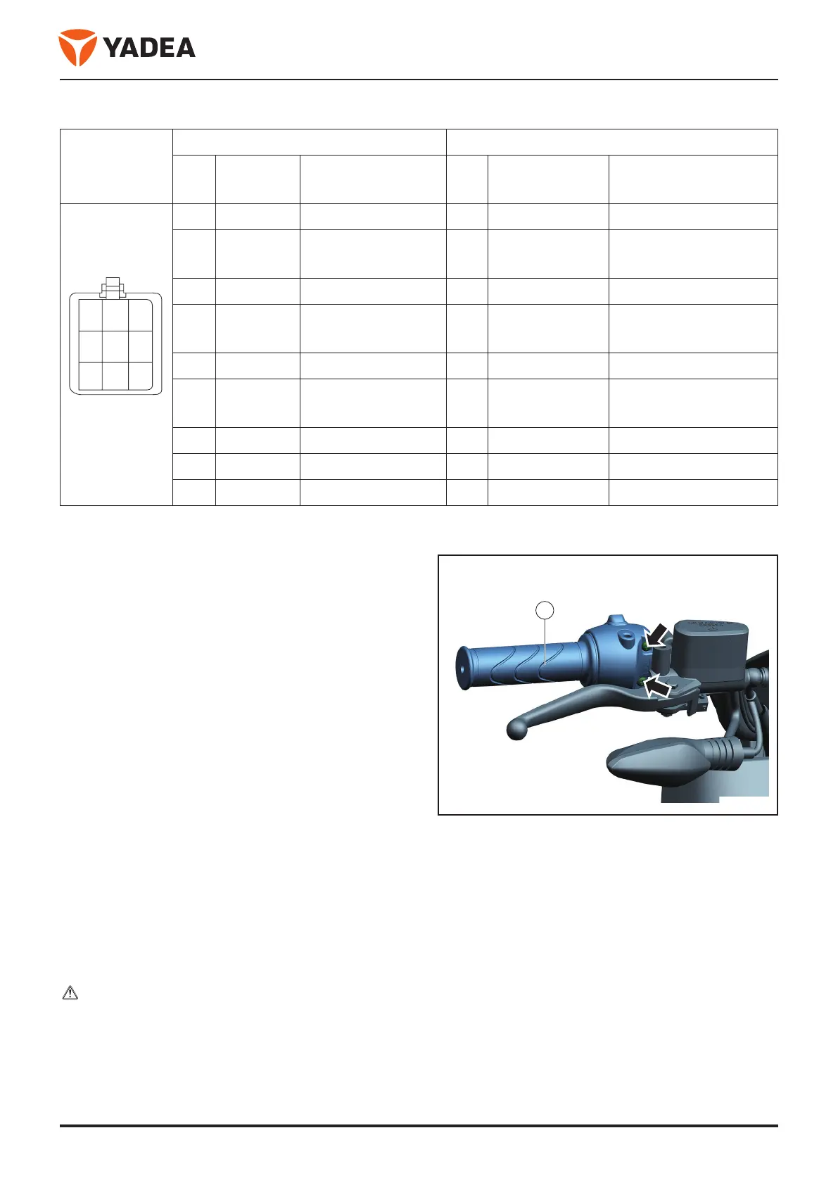
3.2.14 Disassembly and installation the handlebars
3.2.14.1 Overview
For vehicle acceleration or deceleration.
3.2.14.2 Service tools
●
Cross screwdriver
3.2.14.3 Disassembly and installation
Disassembly
●
Park the vehicle on a horizontal road surface to support
the main bracket.
●
Close the key and pull it out.
●
Open the seat cushion and turn off the air switch.
●
Disassembly the hand-held fixed bolts.
●
Disassembly Bolt - Arrow - .
●
Disconnect the adapter connector.
●
Disassembly the handle - 1 -.
Installation
Installation is carried out in reverse order of disas-
sembly.
note
When mounting, the bulge on the housing of the
combined switch - arrow A - is loaded into the hole
on the direction handle - arrow B - inside.
1
5
46
8
97
2
3
1
 Loading...