PREMIUM E-MOBILITY
YD-EM279
34
1
1
5
5
4
4
6
6
2
2
3
3
1
B
A
3.2.12.5 Connector interface definition
Connector No Interface definition Color
1 CAN - H Blue/Black
2 + 12V Black
3 ACC +60V Purple/white
4 / /
5 Lnput 2 Yellow/White
6 CAN - L Green/White
1 High beam Blue
2 Lnput 1 Blue/White
3 GND Green
4 Left turn signal Orange
5 Right turn signal Light blue
6 Smart Keyman Brown/Red
3.2.13 Disassembly and installation combination switch
3.2.13.1 Service tools
●
Cross screwdriver
3.2.13.2 Disassembly and installation
Disassembly
●
Park the vehicle on the level road and support the
main support.
●
Close the key and pull it out.
●
Open the seat cushion and turn off the air switch.
●
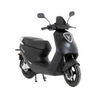
Disassembly the hand-held fixed bolts.
●
Disassembly Bolt - Arrow - .
●
Disconnect the adapter connector.
●
Disassembly the left combo switch - 1 -.
Installation
Installation is carried out in reverse order of disas-
sembly.
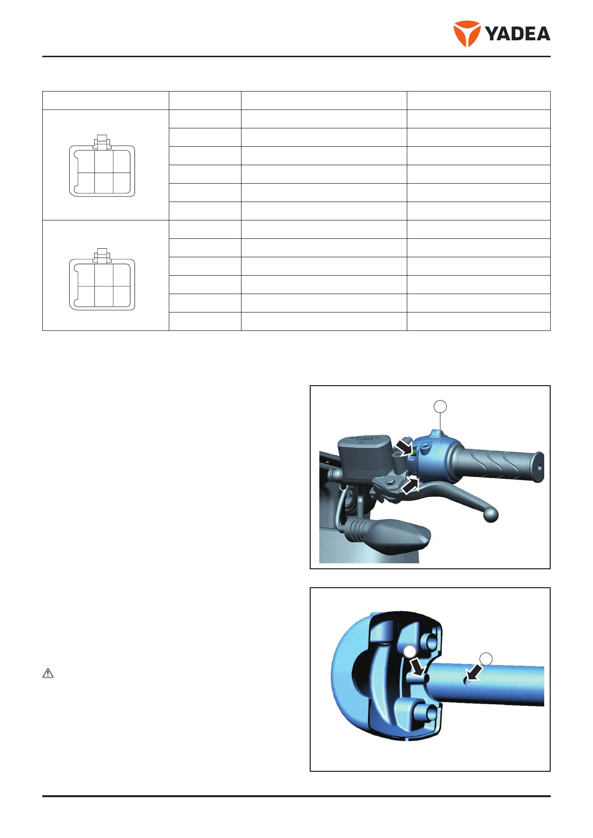
note
When mounting, the bulge on the housing of the
combined switch - arrow A - is loaded into the hole
on the direction handle - arrow B - inside.

 Loading...