ENGINE
3-6
2. Remove:
• Seat
Refer to “GENERAL CHASSIS” on page 4-1.
• Fuel tank
Refer to “FUEL TANK” on page 6-1.
• Air filter case
Refer to “GENERAL CHASSIS” on page 4-1.
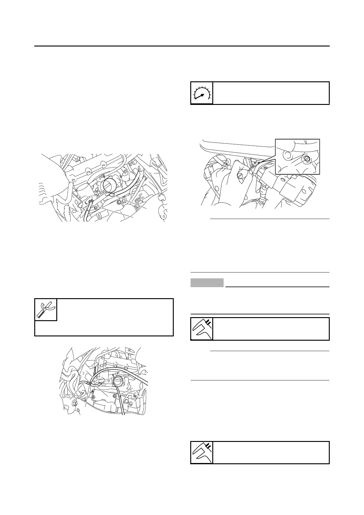
3. Disconnect:
• Intake solenoid vacuum hose (one-way valve
to throttle body) “1”
• Cylinder-#1 intake air pressure sensor hose
“2”
4. Install:
• Fuel hose “1” (Parts No.: 5JW-24311-00)
• 3-way joint “2” (Parts No.: 90413-05014)
• Cylinder-#1 intake air pressure sensor hose
“3”
• Vacuum gauge hose for #1 “4”
• Vacuum gauge hose for #2 “5”
• Vacuum gauge
• Digital tachometer
5. Install:
• Air filter case
Refer to “GENERAL CHASSIS” on page 4-1.
• Fuel tank
Refer to “FUEL TANK” on page 6-1.
6. Adjust:
• Throttle body synchronization
▼▼▼▼▼▼▼▼▼ ▼ ▼▼▼▼ ▼ ▼▼▼▼ ▼ ▼▼▼▼ ▼ ▼▼▼▼ ▼▼▼
a. Start the engine, warm it up for several min-
utes, and then let it run at the specified en-
gine idling speed.
b. With throttle body #1 as standard, adjust
throttle body #2 using the air screw “1” (for
throttle body #2).
NOTE:
• After each step, rev the engine two or three
times, each time for less than a second, and
check the synchronization again.
• If the air screw is removed, turn the screw 3/4
turn in and be sure to synchronize the throttle
body.
CAUTION:
EC5YU1027
Do not use the throttle valve adjusting
screws to adjust the throttle body synchroni-
zation.
NOTE:
The difference in vacuum pressure between two
throttle bodies should not exceed 1.33 kPa (10
mm Hg).
▲▲▲▲▲▲▲▲▲ ▲ ▲▲▲▲ ▲ ▲▲▲▲ ▲ ▲▲▲▲ ▲ ▲▲▲▲ ▲▲▲
7. Stop the engine and remove the measuring
equipment.
8. Adjust:
• Throttle cable free play
Refer to “ADJUSTING THE THROTTLE CA-
BLE FREE PLAY” on page 3-7.
Vacuum gauge
90890-03094
Carburetor synchronizer
YU-44456
1
2
4
2
5
3
1
Engine idling speed
850–950 r/min
Intake vacuum
26.6 kPa (7.9 inHg) (200 mmHg)
Throttle cable free play
3.0–5.0 mm (0.12–0.20 in)
1

 Loading...