2. Inspection and adjustment
64R1
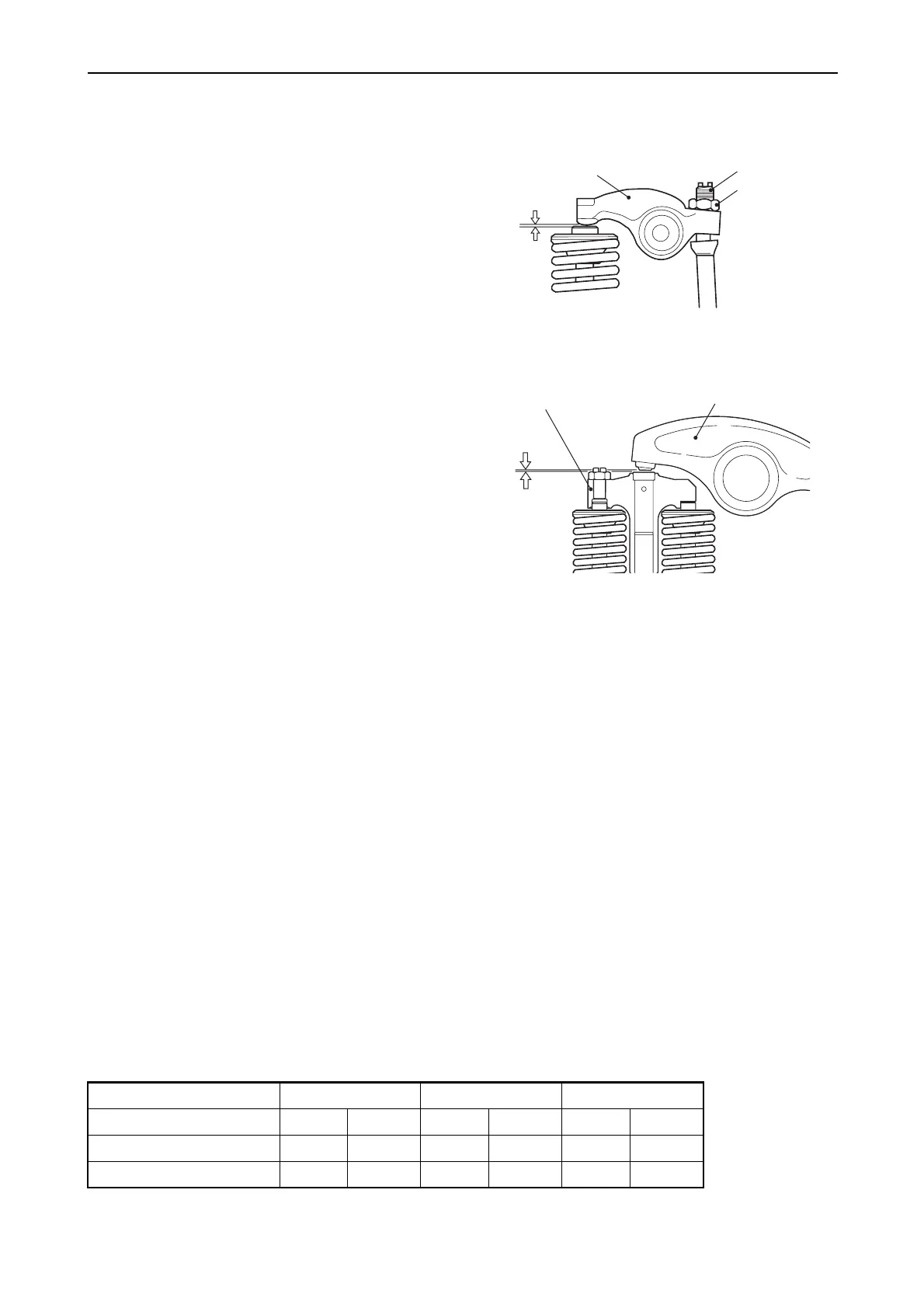
c) Valve clearance measurement and
adjustment
(c-1) For 2 valves system (3JH4E, 4JH4E),
insert a thickness gage between the
rocker arm and valve cap, and record
the measured valve clearance.
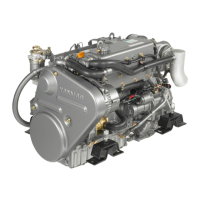
(c-2) For 4 valves system (4JH4-TE, 4JH4-
HTE), insert a thickness gage
between the rocker arm and the valve
bridge, and record the measured
valve clearance.
d) Measuring other cylinders
(d-1) 3JH4E
Turn the crankshaft 240
° and make
measurement and adjustment for the No.3
cylinder. Then adjust the No.2 cylinder.
The cylinder to be measured and adjusted
first does not have to be the No.1 cylinder.
Select and adjust the cylinder where the
piston is the nearest to the top dead center
after turning, and make measurement and
adjustment for other cylinders in the order of
ignition by turning the crankshaft 240
° each
time.
The measurement and adjustment method
of reducing the flywheel turning numbers
(for reference):
Set No.1 cylinder to the compression T.D.C.
and adjust the clearance of the
z mark of
the below table. Next, turn the flywheel
once (the suction/exhaust valve of No.1
cylinder is in the position of the overlap
T.D.C. at this time), and adjust the
clearance of the
{ mark.
Ignition order of 3 cylinder engines: 1
→ 3 →
2
Cylinder No. 1 2 3
Valve Suction Exhaust Suction Exhaust Suction Exhaust
No.1 compression T.D.C zzz zThe first time
No.1 overlap T.D.C {{ The second time
Valve
clearance
Rocker arm
Lock nut
Adjusting screw
010612-00E
2-valve head
Valve
clearance
Rocker arm
Valve bridge
010613-01E
4-valve head