2. Inspection and adjustment
65R1
(d-2) 4JH4E/ 4JH4-TE/ 4JH4-HTE
Turn the crankshaft 180
° and make
measurement and adjustment for the No.3
cylinder. Then adjust the No.4 and No.2
cylinders according to the order of injection.
The cylinder to be adjusted first does not
have to be the No.1 cylinder. Select and
adjust the cylinder where the piston is the
nearest to the top dead center after turning,
and make adjustment for other cylinders in
the order of ignition by turning the
crankshaft 180
° each time.
The measurement and adjustment method
of reducing the flywheel turning numbers
(for reference):
Set No.1 cylinder to the compression T.D.C.
and adjust the clearance of the
z mark of
the bottom table. Next, turn the flywheel
once, and adjust the clearance of the
{
mark.
Ignition order of 4 cylinder engines: 1
→ 3 →
4 → 2
2) Valve clearance adjustment - 2 valves system
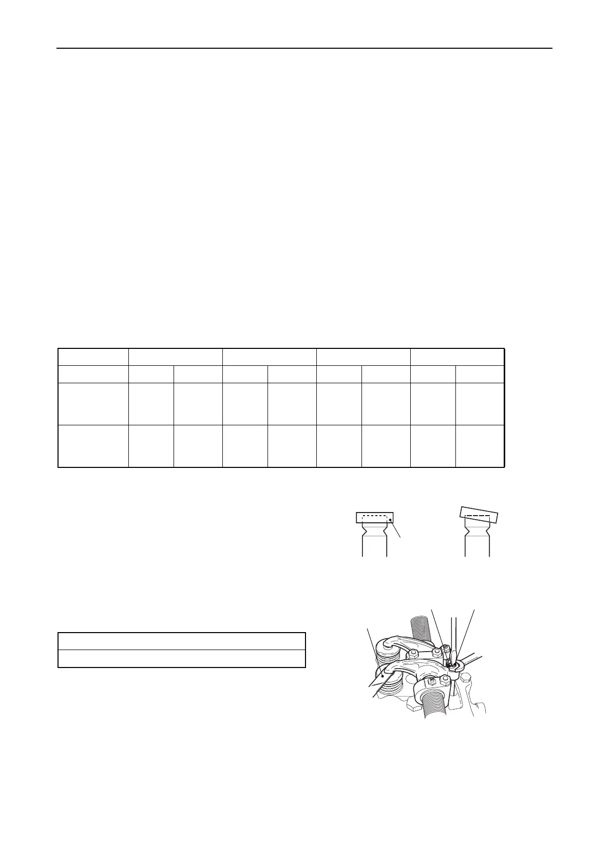
a) Loosen adjusting bolts
Loosen the lock nut and adjusting screw,
and check the valve for any inclination of
valve cap, entrance of dirt or wear.
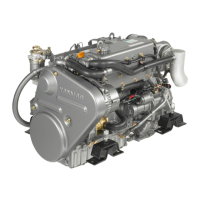
b) Valve clearance adjustment
• Insert a 0.2 mm thickness feeler gauge
between the rocker arm and valve cap.
• Adjust the valve clearance by turning the
adjustment screw until there is a slight
“drag” on the feeler gauge when sliding it
between the rocker arm and the valve cap.
• Tighten the lock nut.
• Apply oil to the contact surface between
adjusting screw and push rod.
c) Adjusting other cylinders
See adjustment method for other cylinders
on page 64.
Cylinder No. 1 2 3 4
Valve Suction Exhaust Suction Exhaust Suction Exhaust Suction Exhaust
No.1
compression
T.D. C
zzz z
The first
time
No.4
compression
T.D. C
{{ {{
The
second
time
Standard intake/exhaust valve clearance (mm)
0.15-0.25
(Normal) (Abnormal)
Valve cap
010614-00E
011215-00E
Feeler gauge
Lock nut Adjusting screw
2 valve cylinder head