Network Communications
10
10.6 MEMOBUS/Modbus Communications
YASKAWA SIEPYAIH6B01A HV600 AC Drive Bypass Technical Reference 745
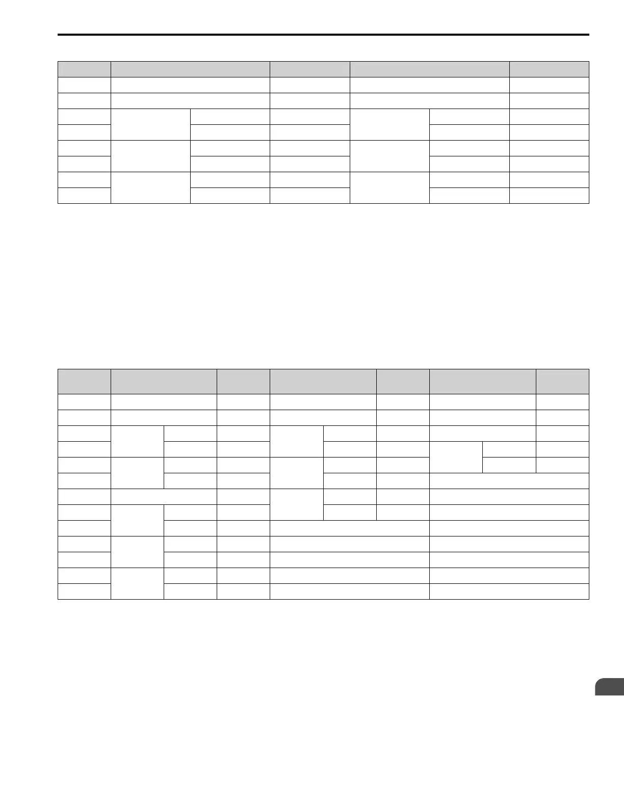
Table 10.24 Message Examples from the Loopback Test
Byte Command Message
Setting Data (Hex.)
Response Message (Normal)
Setting Data (Hex.)
0 Slave address 01 Slave address 01
1 Function code 08 Function code 08
2
Test code
Upper 00
Test code
Upper 00
3 Lower 00 Lower 00
4
Data
Upper A5
Data
Upper A5
5 Lower 37 Lower 37
6
CRC-16
Upper DA
CRC-16
Upper DA
7 Lower 8D Lower 8D
■ Writing to Multiple Holding Registers
Function code 10H lets you write to write multiple MEMOBUS/Modbus registers with one message. This process
works similar to reading registers, in that the address of the first register to be written and the data quantity are set in
the command message. The data to be written must be consecutive so that the register addresses are in order, starting
from the specified address in the command message. The data order must be high byte, then lower byte.
Table 10.25 shows example messages when you use the PLC to set Forward run in the drive of slave 1 with a 60.00
Hz frequency reference.
If parameter values are changed using the Write command, an Enter command is necessary to activate and save the
data. Refer to H5-11: Comm ENTER Command Mode on page 309 and Enter Command on page 748 for more
information.
Table 10.25 Message Example When Writing to Multiple Holding Registers
Byte Command Message
Setting Data
(Hex.)
Response Message (When
Normal)
Setting Data
(Hex.)
Response Message (When
There is a Fault)
Setting Data
(Hex.)
0 Slave address 01 Slave address 01 Slave address 01
1 Function code 10 Function code 10 Function code 90
2
Starting No.
Upper 00
Starting No.
Upper 00 Error code 02
3 Lower 01 Lower 01
CRC-16
Upper CD
4
Data Quantity
Upper 00
Data Quantity
Upper 00 Lower C1
5 Lower 02 Lower 02 -
6 Byte No. 04
CRC-16
Upper 10 -
7
First data
Data Quantity
Upper 00 Lower 08 -
8 Lower 01 - -
9
Next data
Upper 17 - -
10 Lower 70 - -
11
CRC-16
Upper 6D - -
12 Lower B7 - -
Note:
The number of bytes set in the command message set the data quantity × 2 during the command message. The response message uses the
same formula.
■ Reading from More than One Holding Register/Reading the Indicated Register
The bypass uses function code 5A (Hex.) to write to more than one register, then it reads the contents of four holding
registers at the same time.
The function for writing to more than one register is the same as the function for function code 10 (Hex.). You can
write to a maximum of 16 holding registers.
The four holding registers to be read from are specified in H5-25 to H5-28 [Function 5A Register x Selection].

 Loading...


