D.1
Fixed Parameter List
A-19
D Motion Parameter Lists
The motion parameters (fixed parameters, setting parameters, and monitoring parameters) for SVB and SVR Modules
are listed below.
For information on how to use each motion parameter, refer to Machine Controller MP2000 Series Built-in SVB/SVB-
01 Motion Modules User’s Manual (Manual No.: SIEPC88070033).
The Yes in the SVB or SVR column indicates that the motion parameter is supported by the corresponding module.
The parameters whose register numbers are marked with an asterisk (*) are valid only when using an MP2300CPU
Ver 2.61 or later and
Σ
-
V
series servo drive.
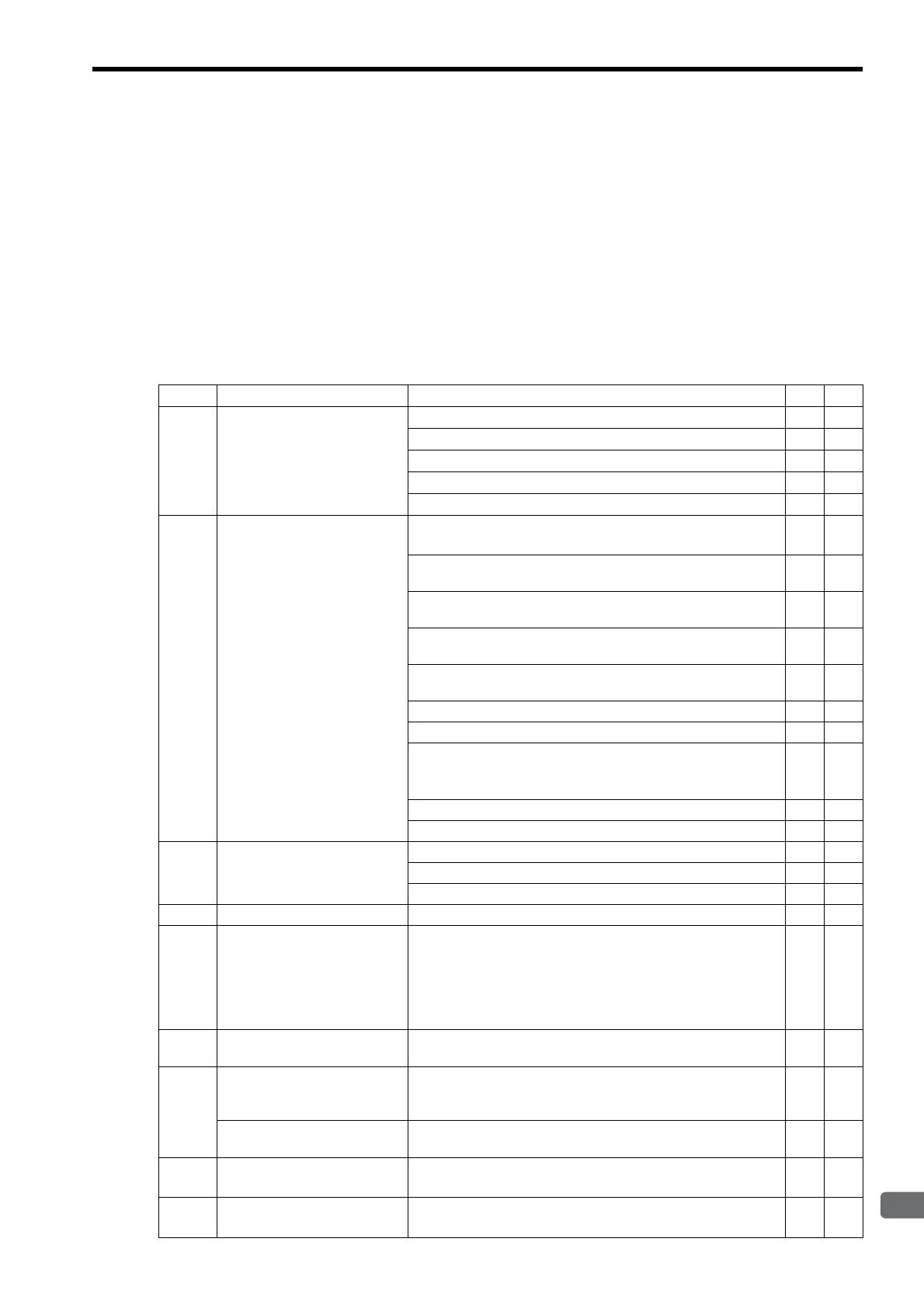
D.1 Fixed Parameter List
No. Name Contents SVB SVR
0
Selection of Operation Modes
0: Normal Operation Mode
Yes Yes
1: Axis unused
Yes Yes
2: Simulation mode
Yes
3: Servo Driver Transmission Reference Mode
Yes
4 and 5: Reserved for system use.
−−
1
Function Selection Flag 1
Bit 0: Axis Selection (0: Finite length axis/1: Infinite length axis)
Set to 0 for linear type.
Yes Yes
Bit 1: Soft Limit (Positive Direction) Enable/Disable
(0: Disabled/1: Enabled)
Yes
Bit 2: Soft Limit (Negative Direction) Enable/Disable
(0: Disabled/1: Enabled)
Yes
Bit 3: Overtravel Positive Direction Enable/Disable
(0: Disabled/1: Enabled)
Yes
Bit 4: Overtravel Negative Direction Enable/Disable
(0: Disabled/1: Enabled)
Yes
Bits 5 to 7: Reserved for system use.
−−
Bit 8: Interpolation Segment Distribution Processing
Yes
Bit 9: Simple ABS Rotary Pos. Mode (Simple absolute infinite axis
position control) (0: Disabled/1: Enabled)
Set to 0 for linear type.
Yes
Bit A: User Constants Self-writing Function
Yes
Bits B to F: Reserved for system use.
2
Function Selection Flag 2
Bit 0: Communication Abnormality Detection Mask
Yes
Bit 1: WDT Abnormality Detection Mask
Yes
Bits 2 to F: Reserved for system use.
−−
3
−
Reserved for system use.
−−
4
Reference Unit Selection
0: pulse 3: inch
1: mm 4: μm
2: deg
For linear type, 0 (pulse), 1 (mm), and 4 (
μ
m) can be used.
If 2 (deg.) or 3 (inch) is selected, the selected unit will be
converted to mm.
Yes Yes
5
Number of Digits below
Decimal Point
1 = 1 digit
Yes Yes
6
Travel Distance per Machine
Rotation
(rotary motor)
1 = 1 reference unit
Yes Yes
Linear Scale Pitch
(linear motor)
1 = 1 reference unit
Yes Yes
8
Servo Motor Gear Ratio
1 = 1 rotation
Invalid for linear type
Yes Yes
9
Machine Gear Ratio
1 = 1 rotation
Invalid for linear type
Yes Yes