3
Mounting and Connections
3.1.1
Basic Module Dimensional Drawings
3-2
3.1 Mounting the MP2300
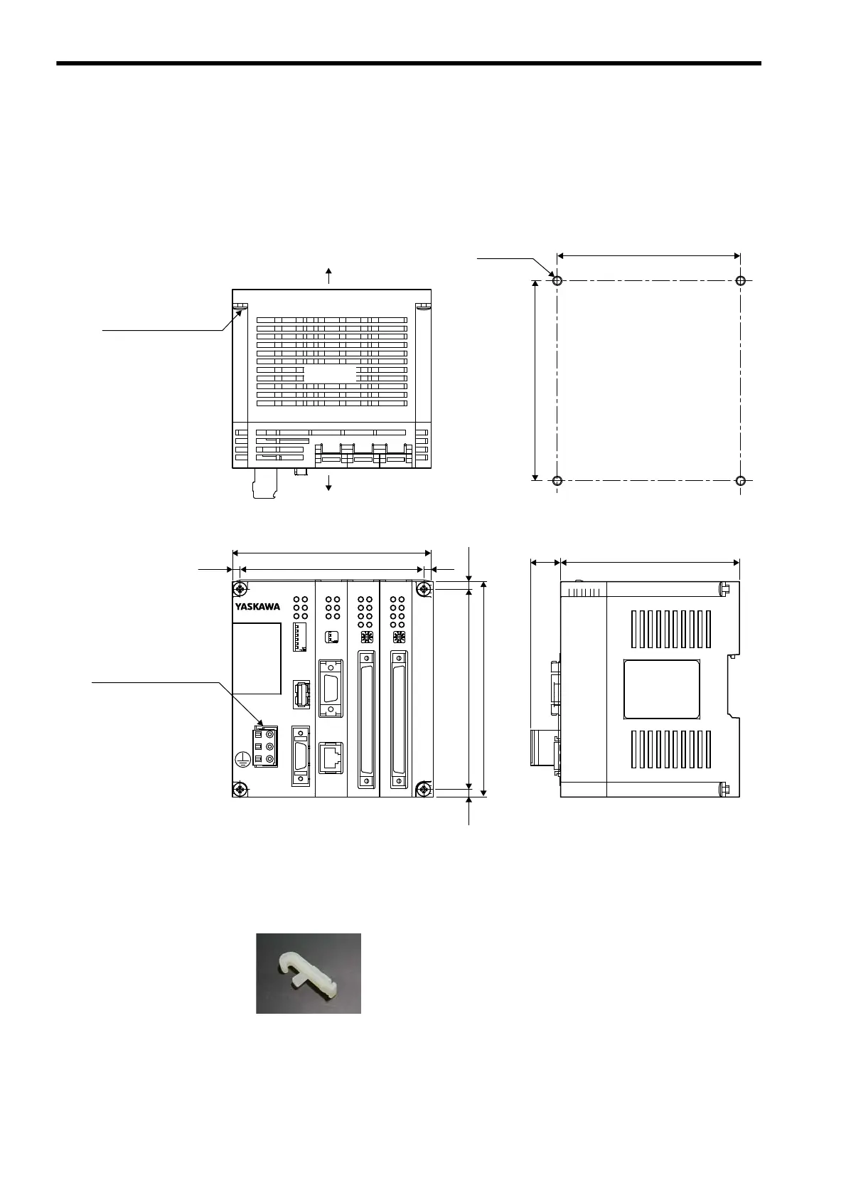
3.1.1 Basic Module Dimensional Drawings
Refer to the following dimensions for installation.
A 721-203/026-000 Cable Connector is mounted to the POWER connector.
Use this connector and twisted-pair cable and prepare the power cable. Refer to 3.2.2 ( 2 ) Assembling the 24-VDC
Power Supply Cable on page 3-11 for details.
Accessesory: Operation lever type 231-131
The operation lever is used when connecting wires to the cable connector.
218IF-01
ERR
COL
RX
RUN
STRX
TX
INIT
TEST
OFF ON
PORT
10Base-T
LIO-01
LD5
LD6
LD7
LD8LD4
LD3
LD2
LD1
MODE
I/O
LIO-01
LD5
LD6
LD7
LD8LD4
LD3
LD2
LD1
MODE
I/O
RUN
ERR
BAT
SW1
OFF
RDY
ALM
TX
STOP
SUP
INIT
CNFG
MON
TEST
ON
BATTERY
CPU I/O
POWER
DC 0V
DC24V
(4.5)
130
1214.5
(18)
108
120
111
4.5
(4.5)
111±0.2
121±0.2
Panel Cutout Dimensions
Rear
Front
Front view Right side view
Four-M4 tap
M4 mounting screws (4)
Cable connector (3P)
721-203/026-000
M-I/II
MP2300
Units: mm
Top view