2.2
MP2300 Basic Module Functions
2-7
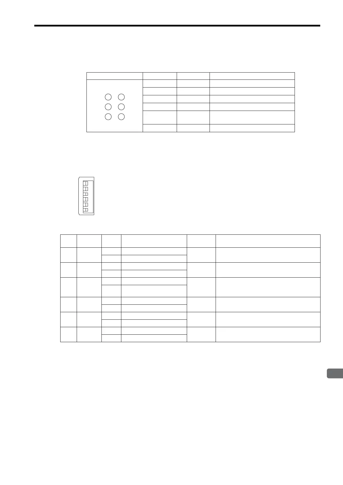
( 2 ) Indicators
The following table shows the indicators that show the operating status of the Basic Module and error information.
For details on indicator meanings, refer to 6.3.3 ( 2 ) LED Indicator Meanings on page 6-7.
( 3 ) Switch Settings
The DIP switch sets the operating conditions for the Basic Module when the power is turned ON.
Indicator Color Status
RDY
Green
Lit during normal operation.
RUN
Green
Lit during execution of user program.
ALM
Red
Lit/blinking when warning occurs.
ERR
Red
Lit/blinking when malfunction occurs.
TX
Green
Lit during transmission of
MECHATROLINK I/II data.
BAT
Red
Lit during battery alarm.
SW1
OFFޓޓޓON
STOP
SUP
INIT
CNFG
MON
TEST
123456
No. Name Setting Operating Mode
Default
Setting
Details
6
STOP
ON User program stopped
OFF
Stops the user program execution. Enabled only
when the power is turned ON.
OFF User program running
5
SUP
ON System use
OFF
Always leave set to OFF.
OFF Normal operation
4
INIT
ON Memory clear
OFF
Set to ON to clear the memory. If this switch is set
to OFF, the program stored in flash memory will
be executed.
OFF Normal operation
3
CNFG
ON Configuration mode
OFF
Set to ON to execute self-configuration for
connected devices.
OFF Normal operation
2
MON
ON System use
OFF
Always leave set to OFF.
OFF Normal operation
1
TEST
ON System use
OFF
Always leave set to OFF.
OFF Normal operation