3.2
Basic Module Connections Specifications
3-19
3
Mounting and Connections
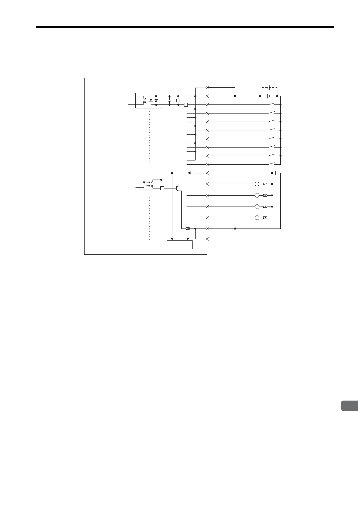
( 7 ) CPU I/O Connector Connections
The following diagram shows the connections for the CPU I/O connector.
Connect a fuse suitable for the load specifications in the output signal circuit in series with the load. If an
external fuse is not connected, load shorts or overloads could result in fire, destruction of the load device, or
damage to the output element.
The pins 1 and 11 and the pins 8 and 18 are internally connected. Connect them externally as well.
Digital input
Digital output
External
input
signals
24 VDC
24 VDC
External
ouput
signals
11
Fuse
Fuse
L
L
L
L
DI_00
DI_01
DI_02
DI_03
DI_04
DI_05
DI_06
DI_07
DO_24V
DO_00
DO_01
DO_02
DO_03
DO_COM
DO_COM
2
3
4
5
12
13
14
15
1
17
9
10
19
20
8
18
DI_COM
DI_COM
R
R
R
Fuse blowout
detection circuit