9.2 List of Parameters
9.2.2 List of Parameters
9-41
*1. Refer to the following manual for details.
Σ-7-Series Σ-7S SERVOPACK with Analog Voltage/Pulse Train References Product Manual
(Manual No.: SIEP S800001 26)
*2. Set a percentage of the rated motor torque.
*3. The setting of Pn502 is used for the stop condition for the motor. Set it to a suitable value for the system.
*4. These parameters are for SERVOPACKs with a Safety Module. Refer to the following manual for details.
Σ-V-Series/Σ-V-Series for Large-Capacity Models/Σ-7-Series User’s Manual Safety Module
(Manual No.: SIEP C720829 06)
*5. Normally set this parameter to 0. If you use an External Regenerative Resistor, set the capacity (W) of the Exter-
nal Regenerative Resistor.
*6. The upper limit is the maximum output capacity (W) of the SERVOPACK.
*7. These parameters are for SERVOPACKs with the Dynamic Brake Option. Refer to the following manual for
details.
Σ-7-Series AC Servo Drive Σ-7S/Σ-7W SERVOPACK with Dynamic Brake Hardware Option Specifications Prod-
uct Manual (Manual No.: SIEP S800001 73)
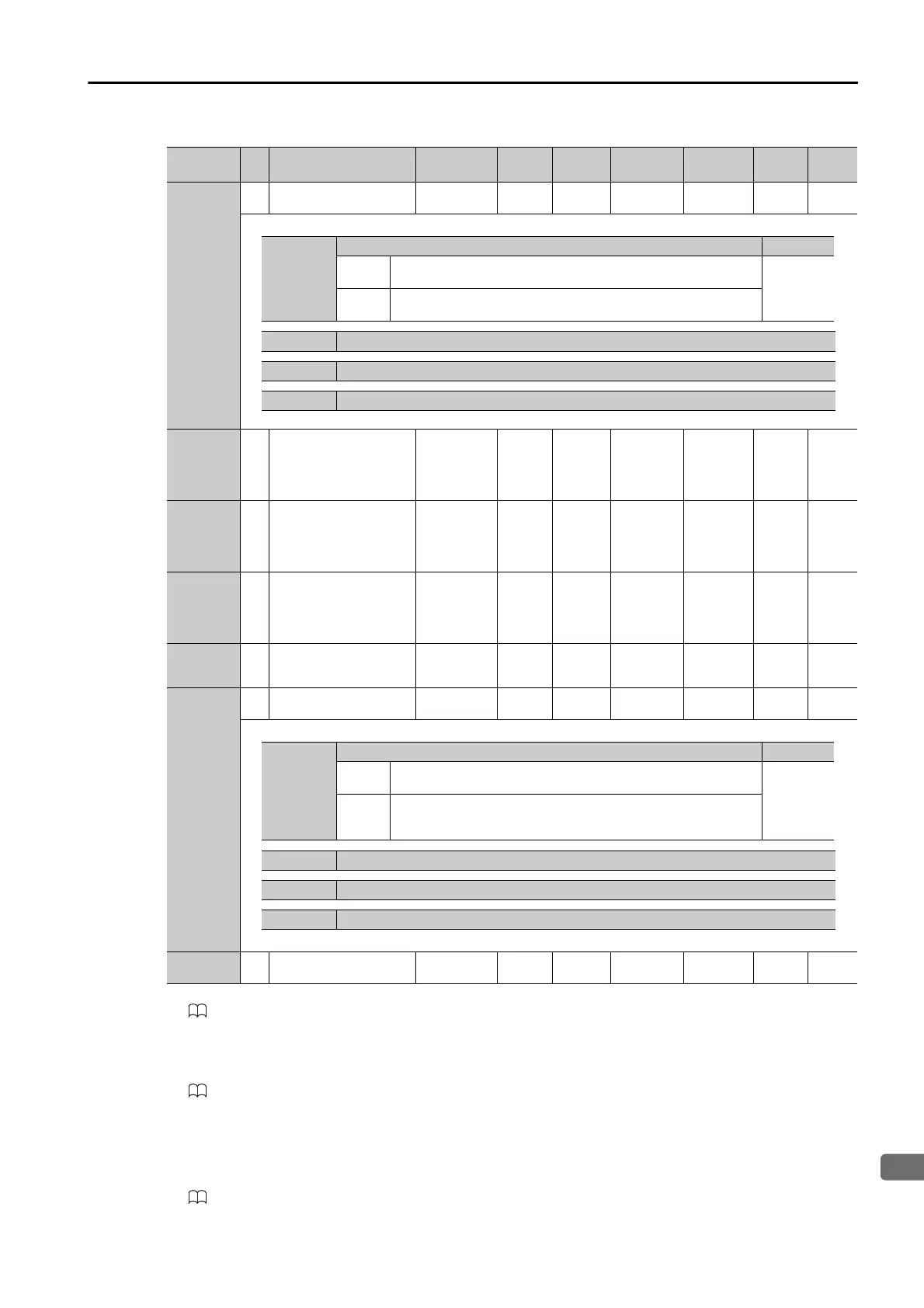
Pn643
2 Homing Direction
0000h to
0001h
– 0000h All
Immedi-
ately
––
Pn644 4
Homing Movement
Speed
1 to
199,999,999
1,000
refer-
ence
units/
min
-1
1000 All
Immedi-
ately
Setup
page
7-5
Pn646 4 Origin Approach Speed
1 to
199,999,999
1,000
refer-
ence
units/
min
-1
1000 All
Immedi-
ately
Setup
page
7-5
Pn648 4 Homing Creep Speed
1 to
199,999,999
1,000
refer-
ence
units/
min
-1
1000 All
Immedi-
ately
Setup
page
7-6
Pn64A 4
Homing Final Travel
Distance
-1,073,741,823
to
+1,073,741,823
Refer-
ence
units
0All
Immedi-
ately
Setup
page
7-6
Pn64C
2 ZONE Signal Setting
0000h to
0001h
– 0000h All
After
restart
Setup –
Pn64D 2
Reserved parameter (Do
not change.)
– – 0000 – – – –
Continued from previous page.
Parameter
No.
Size
Name
Setting
Range
Setting
Unit
Default
Setting
Applicable
Motors
When
Enabled
Classi-
fication
Refer-
ence
n.X
Homing Direction Reference
0
When the /HOME signal turns ON, homing is performed in the
forward direction.
page 7-5
1
When the /HOME signal turns ON, homing is performed in the
reverse direction.
n.X Reserved parameter (Do not change.)
n.X Reserved parameter (Do not change.)
n.X Reserved parameter (Do not change.)
n.X
ZONE Signal Setting Reference
0
When the control power supply is turned ON or the SERVOPACK
is reset, the /POUT0 to /POUT2 signals are inactive.
page 7-54
1
When the control power supply is turned ON or the SERVOPACK
is reset, the /POUT0 to /POUT2 signals are used as ZONE sig-
nals.
n.X Reserved parameter (Do not change.)
n.X Reserved parameter (Do not change.)
n.X Reserved parameter (Do not change.)

 Loading...


