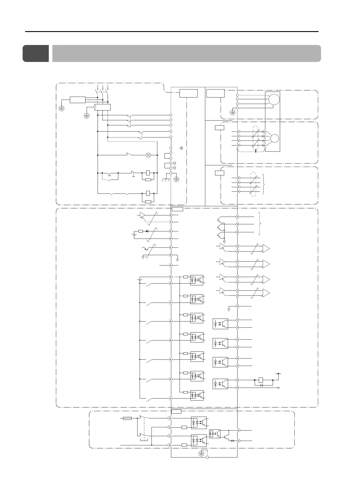
This section provide the basic wiring diagrams. Refer to the reference sections given in the dia-
BAT(+)
BAT(-)
PBO
PCO
/PBO
PAO
/PAO
/PCO
/SO1+
(/COIN+)
/SO1-
(/COIN-)
/SO2+
(/S-RDY+)
/SO2-
(/S-RDY-)
/SO3+
(/BK+)
ALM+
ALM-
EDM1+
EDM1-
FG
22
21
27
28
29
30
31
32
25
26
19
33
34
35
36
20
+24 V
+24VIN
/SI0 (/S-ON)
/SI3 (/MODE 0/1)
/SI1 (/START-STOP,
/HOME)
/SI2 (/JOGP,
SEL0)
/SI4
(/JOGN, SEL1)
/SI6 (/PGMRES,
/ALM-RST)
47
41
43
42
44
45
/SI5
(/JOG0, SEL2)
46
40
/SO3-
(/BK-)
1
SG
2
+5 V
0 V
SEN
SG
4
*4
TH
50
/POUT0
/POUT1
/POUT2
37
38
39
/HWBB1+
/HWBB1-
/HWBB2+
/HWBB2-
24 V
0 V
6
3
4
5
8
7
PSO
/PSO
48
49
*6
*1
*6
*6
*6
DEC
14
15
*1
*1
CN1
CN8
+
-
1
2
5
6
ENC
PS
/PS
PG5V
PG0V
2
4
1
3
0 V
1Ry
1D
+24 V
CN5
L1
U
V
W
M
B2
B3
L2
L1C
L3
L2C
1
2
B1/
2KM
1KM
1QF
R
S T
1FLT
3SA
1PL
1KM
2KM
1SA
2SA
1KM
1Ry
1KM
1Ry
CN2
Battery for absolute
encoder
*2
2.8 V to 4.5 V
Connect shield to connector shell.
Connector shell
Ground to
a resistance
of 100 Ω
or less.
Switch
Fuse
Safety
Encoder Divided
Pulse Output,
Phase A
Encoder Divided
Pulse Output,
Phase B
Encoder Divided
Pulse Output,
Phase C
*5
Absolute encoder
position output
*2
General-purpose sequence input 0
(Servo ON input: ON to turn ON servo)
Sequence input signal
power supply input
Overheat protection input
Frame ground
Servo Alarm output
Signal ground
Absolute data
request input
Main circuit
terminals
Analog Monitors
SERVOPACK
(For servo alarm
display)
Servo power
ON
Servo power
OFF
Motor
terminals
General-purpose sequence input 8
(Homing Deceleration Switch input:
Deceleration when ON)
General-purpose sequence input 2
(Forward Jog input:
Forward jog operation when ON)
General-purpose sequence input 1
(Program Table Operation Start-Stop input:
Program table operation starts when ON)
General-purpose sequence input 4
(Reverse Jog input:
Reverse jog operation when ON)
General-purpose sequence input 6
(Program Table Operation Reset input:
Program table operation reset for ON)
General-purpose sequence input 5
(Jog Speed Table Selection input:
Jog operation when ON)
General-purpose sequence input 3
(Mode Switch input: Program Table
Operation Mode when ON)
General-purpose sequence output 2
(Servo Ready output:
ON when /S-ON signal can be received)
General-purpose sequence output 3
(Brake output: OFF to apply brake)
General-purpose sequence output 1
(Positioning Completion output;
Positioning completed when ON)
Programmable outputs
SI8(DEC)
/SI8(/DEC)

 Loading...


