3.2 I/O Signal Connections
3.2.3 I/O Circuits
3-9
3
Wiring and Connecting SERVOPACKs
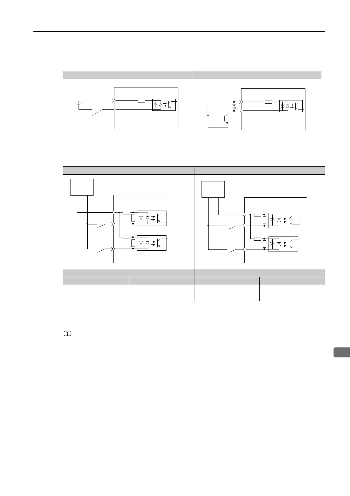
This section describes CN1 connector terminals 40 to 47. The circuits are connected through
relay or open-collector transistor circuits. If you connect through a relay, use a low-current
relay. If you do not use a low-current relay, a faulty contact may result.
Note: The 24-VDC external power supply capacity must be 50 mA minimum.
The SERVOPACK input circuits use bidirectional photocouplers. Select either a sink circuit or
source circuit according to the specifications required by the machine.
Sequence Output Circuits
Refer to the following manual for details on sequence circuit outputs.
Σ-7-Series Σ-7S SERVOPACK with Analog Voltage/Pulse Train References Product Manual (Manual No.: SIEP
S800001 26)
Examples for Relay Circuits Examples for Open-Collector Circuits
Sink Circuits Source Circuits
Input Signal Polarity Input Signal Polarity
Photocoupler Internal Signal Level Photocoupler Internal Signal Level
ON Low level ON Low level
OFF High level OFF High level
4.7 kΩ
E.g., /S-ON
SERVOPACK
24 VDC
+24VIN
24 VDC
4.7 kΩ
E.g., /S-ON
SERVOPACK
+24VIN
SERVOPACK input side
Switch
Photocoupler
Internal
signal
level
Internal
signal
level
Photocoupler
Switch
24 V
+
−
SERVOPACK input side
24 V
+
−
Switch
Photocoupler
Internal
signal
level
Internal
signal
level
Photocoupler
Switch

 Loading...


