3.2 Setting User Constants According to Host Controller
89
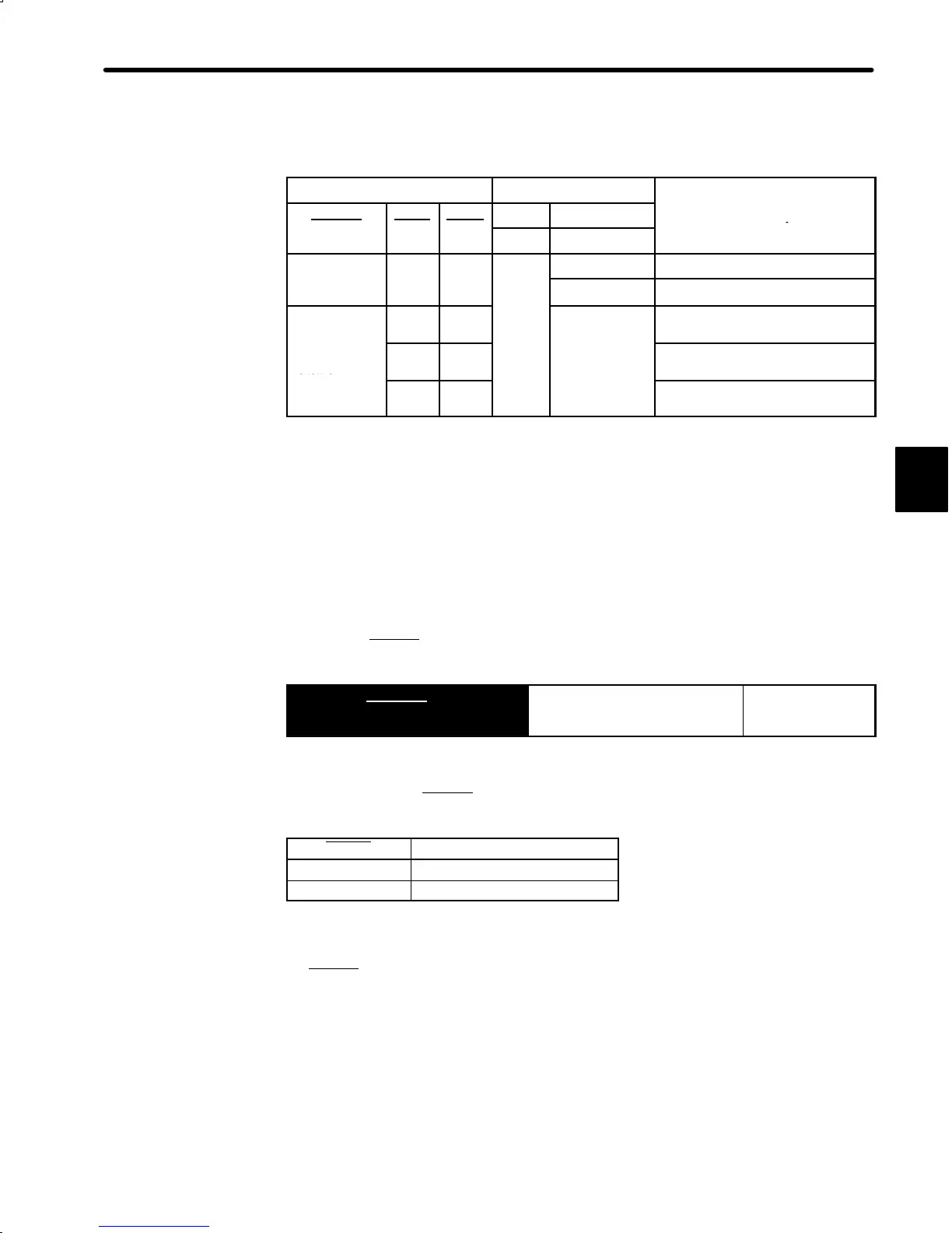
• For Position Control:
0: OFF, 1: ON
Contact Signal
User Constant
Cn-02 Cn-01
Selected Speed
-
-
-
Bit 2 Bit F
0 Stop
−−−−
u
se re
erence
npu
Direction of
rotation
0 1
1
SPEED (Cn-1F)
0: Forward
rotation
1 1
−−−−
SPEED (Cn-20)
1: Reverse
rotation
1 0 SPEED (Cn-21)
Preset values (0 or 1) and input signal status in the portions indicated by horizontal
bars (−) are optional.
Note
When the contact input speed control function is used, the reference pulse inhibit
function is not available.
b) Standard Setting when Cn-02 bit 2 = 0
Input signals are used as external torque limit input.
Input signal P-CON
is used to specify the direction of motor rotation.
→ Input P-CON 1CN-41
Proportional Control, etc. For Speed/Torque
Control and
Position Control
a) Contact Input Speed Control when Cn-02 bit 2 = 1
Use input signal P-CON
to specify the direction of motor rotation.
P-CON Meaning
1 Reverse rotation
0 Forward rotation
0: OFF (high level), 1: ON (low level)
b) Standard Setting when Cn-02 bit 2 = 0
P-CON
signal is used for proportional control, zero-clamp and torque/speed control
changeover.
Note For the speed/torque control, control by external reference (voltage reference) is
possible when the contact input speed control function is used by setting bits A
and B of user constant Cn-01.
For the position control, control by external reference (pulse reference) is pos-
sible when the contact input speed control function is used by setting bit F of user
constant Cn-01.
3

 Loading...


