3.7 Forming a Protective Sequence
133
3.7.3 Using Positioning Complete Signal
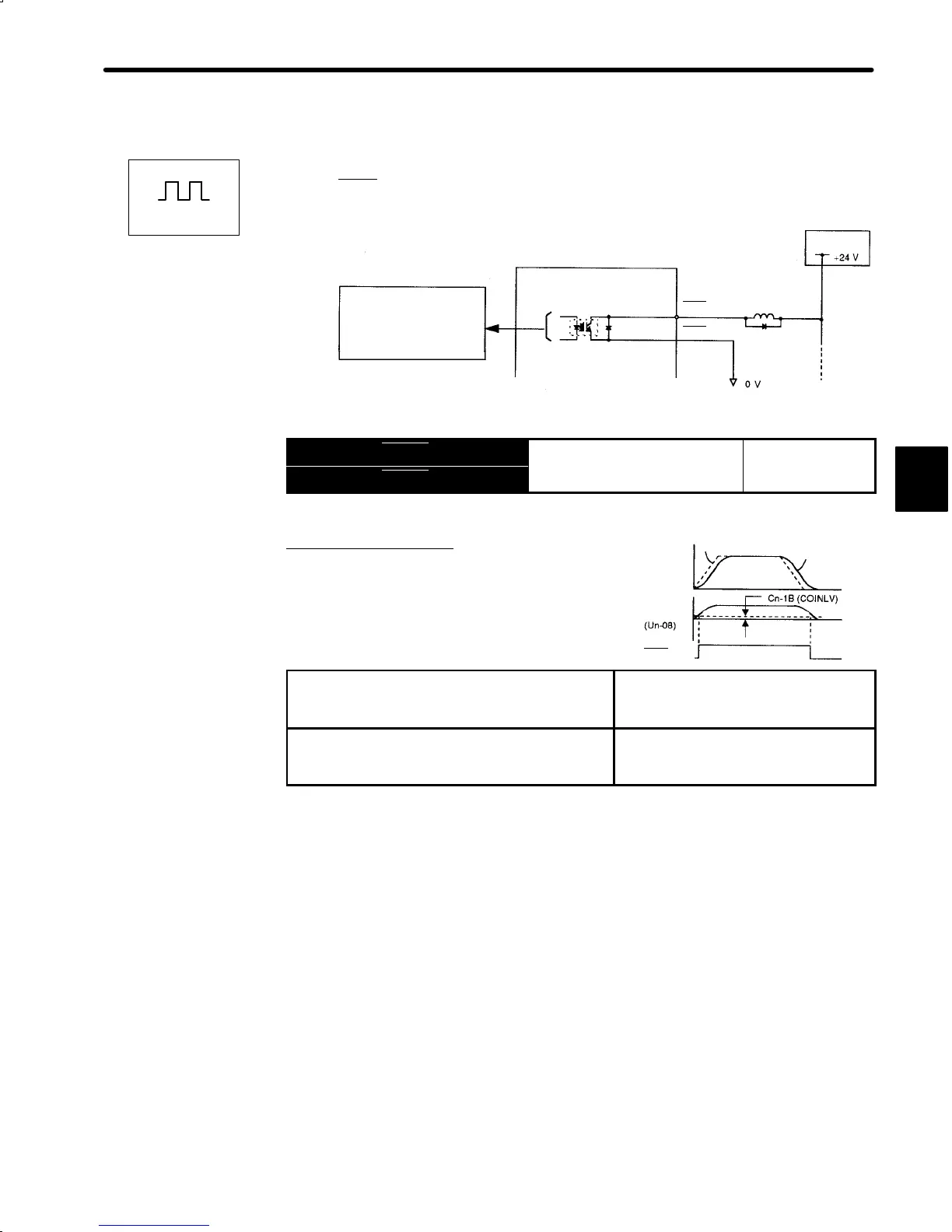
1) This section describes how to wire and use contact output-signal “positioning complete
output (COIN
).” This signal is output to indicate that servomotor operation is complete.
Photocoupler output
Per output:
Maximum operation voltage:
30 VDC
Maximum output current:
50 mADC
Servopack
I/O power
supply
1CN-25
1CN-26
COIN
+
COIN-
Output → COIN+ 1CN-25
Positioning Complete Output
For Position
Output → COIN- 1CN-26
Control Only
For position control only.
This output signal indicates that motor operation
is complete during position control. The host con-
troller uses this signal as an interlock to confirm
that positioning is complete.
ON
status:
Circuit between 1CN-25 and 1CN-26 is
closed.
1CN-25 is at low level.
Positioning is complete (position error is
below the preset value).
OFF
status:
Circuit between 1CN-25 and 1CN-26 is
open.
1CN-25 is at high level.
Positioning is not complete (position
error is over the preset value.)
Preset Value: Cn-1B (positioning complete range)
2) Set the number of error pulses in the following user constant Cn-1B to adjust output tim-
ing of COIN (positioning complete output).
3
Positions
Speed
Reference
Motor
Error
pulse
COIN
+
(1CN-25)

 Loading...


