APPLICATIONS OF Σ-SERIES PRODUCTS
3.7.6 Using Servo Ready Output
138
3) Use the following user constant to specify the output conditions for running output signals
TGON
+, TGON-.
Cn-0B TGONLV
Zero-Speed
Level
Unit:
r/min
Setting
Range: 1 to
Maximum
Speed
Factory
Setting:
20
For
Speed/Torque
Control and
Position Control
This user constant is used to set the speed level at which the Servopack determines that
the motor is running and then outputs a signal.
The following signals are output when motor speed exceeds the preset value. (The circuit
between 1CN-27 and 1CN-28 is closed when motor speed exceeds the preset value.)
Signals are output when motor speed exceeds the preset value.
D TGON
+ (1CN-27)
D Status indication mode bit data
D Monitor mode Un-05 bit 4
User Constant Setting:
Memory switch Cn-01 bit E = 0
3.7.6 Using Servo Ready Output
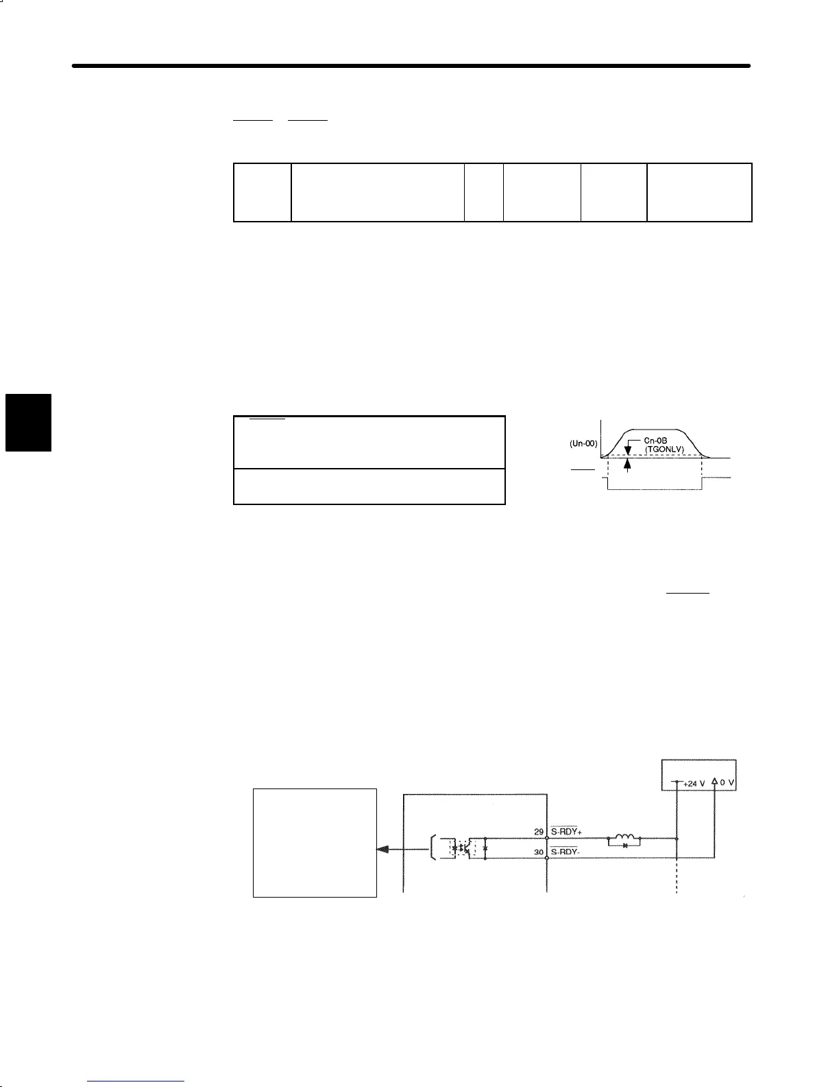
1) This section describes how to wire and use photocoupler output signal S-RDY (servo
ready).
“Servo ready” means that the Servopack is not in servo alarm state when the main circuit
is turned ON. For absolute encoder specifications, “servo ready” means that, in addition
to the above, the SEN signal is at high level and the absolute encoder is also in ready
state.
Also, alarm state is reset at control power ON/OFF.
3
Motor
speed
TGON+
(1CN-27)
Photocoupler output
Per output
Maximum operational
voltage: 30VDC
Maximum output
current: 50mADC
Servopack
24V power
supply
 Loading...


