APPLICATIONS OF Σ-SERIES PRODUCTS
3.2.3 Using Encoder Output
76
3.2.3 Using Encoder Output
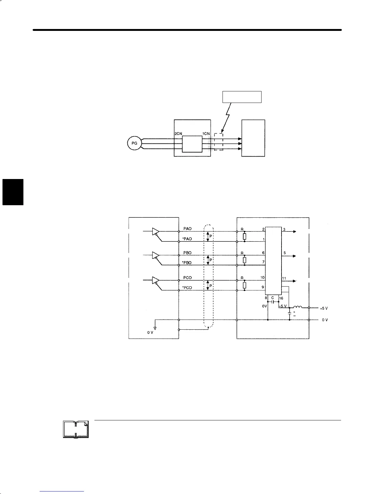
1) Encoder output signals divided inside the Servopack can be output externally. These
signals can be used to form a position control loop in the host controller.
Servomotor
encoder
Servopack
Frequency
dividing
circuit
Host
controller
This output is
explained here.
Phase A
Phase B
Phase C
The output circuit is for line driver output. Connect each signal line according to the fol-
lowing circuit diagram.
Servopack
Host controller
Line receiver
Choke
coil
Smoothing
capacitor
Line receiver used: SN75175 manufactured by
Texas Instruments Inc. or
MC3486 (or equivalent)
R (termination resistor): 220 to 470 Ω
C (decoupling capacitor): 0.1 μF
↕P: Represents twisted-pair cables
Phase A
Phase B
Phase C
Phase A
Phase B
Phase C
(1CN-33)
(1CN-34)
(1CN-35)
(1CN-36)
(1CN-19)
(1CN-20)
(1CN-1)
(1CN-50)
SG
FG
4
12
D
TERMS
Divided (or dividing)
“Dividing” means converting an input pulse train from the encoder mounted on the motor
according to the preset pulse density and outputting the converted pulse. The unit is pulses
per revolution.
3
 Loading...


