3.2 Setting User Constants According to Host Controller
77
2) I/O signals are described below.
Output → PAO 1CN-33
Encoder Output
Phase-A
For Speed/Torque Control
and Position Control
Output →
£
PAO 1CN-34
Encoder Output
Phase-A
For Speed/Torque Control
and Position Control
Output → PBO 1CN-35
Encoder Output
Phase-B
For Speed/Torque Control
and Position Control
Output →
£
PBO 1CN-36
Encoder Output
Phase-B
For Speed/Torque Control
and Position Control
Output → PCO 1CN-19
Encoder Output
Phase-C
For Speed/Torque Control
and Position Control
Output →
£
PCO 1CN-20
Encoder Output
Phase-C
For Speed/Torque Control
and Position Control
Divided encoder signals are output.
Always connect these signal terminals when a position loop is formed in the host control-
ler to perform position control.
Set a dividing ratio in the following user constant.
Dividing ratio setting Cn-0A PGRAT
The dividing ratio setting is not relevant to the gear ratio setting (Cn-24, 25) for the
electronic gear function of the Servopack for position control.
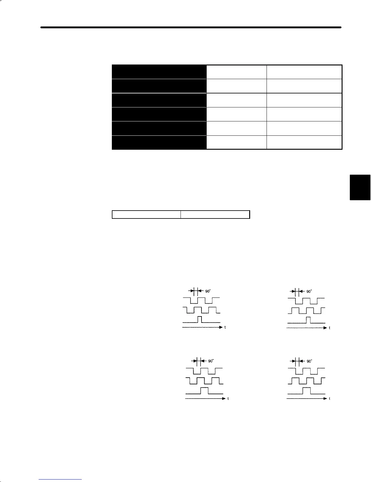
Output Phase Form
Forward rotation Reverse rotation
(Incremental Encoder)
Phase A
Phase B
Phase C
Phase A
Phase B
Phase C
(Absolute Encoder)
Forward rotation Reverse rotation
Phase A
Phase B
Phase C
Phase A
Phase B
Phase C
3

 Loading...


