SERVO SELECTION AND DATA SHEETS
5.6.14 Encoder Signal Converter Unit cont.
380
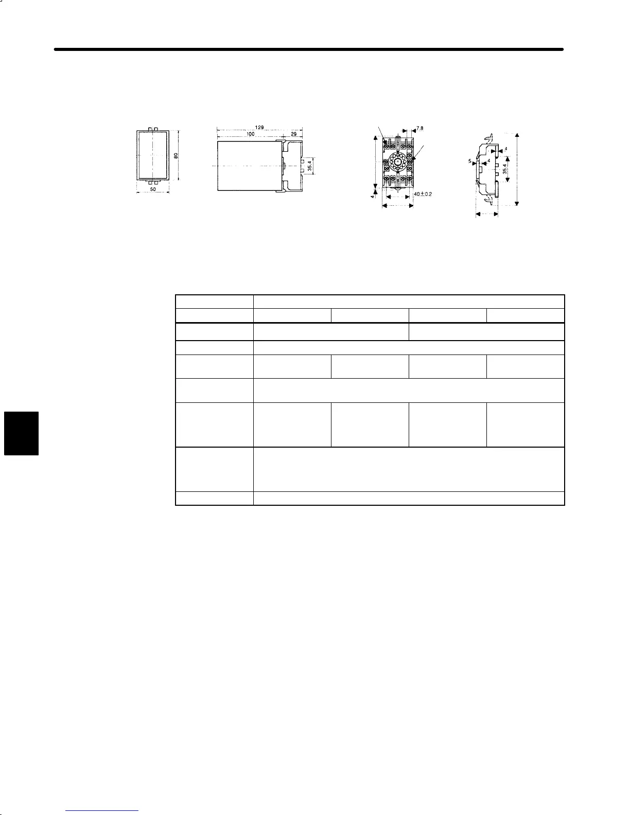
• Dimensional Drawings
11 − M3.5 x 7
Seams screws
51 max.
(2.01)
Holes 2 x
4.5 mm dia.
(Φ0.18)
33.5 max.
(1.32)
118 max.
(4.65)
(1.97)
(5.08)
(3.94) (0.75)
(3.15)
(1.39)
(0,16) 81max(3.19)
(0.31)
(0.20)
(0.16)
(0.16)
(1.39)
(1.57¦0.0079)
2) The encoder signal converter unit specifications are as follows:
Type Receiver Unit
Spec. LRX-01/A1 LRX-01/A2 LRX-01/A3 LRX-01/A4
Power Supply
12 VDC 10%, 100 mA 5 VDC 10%, 100 mA
Input Signals Balanced line driver input (RS-422)
Output Signals Voltage pulse
output
Open collector
output
Voltage pulse
output
Open collector
output
Input Signal
Level
Voltage differential ≥ 0.3 V, internal termination resistance 100 Ω
Output Signal
Level
H: 10 V min.
(1 mA)
L: 0.5 V max.
(30 mA)
L: 0.5 V max.
(30 mA)
Withstand
voltage: 50 V
H: 3 V min.
(1 mA)
L: 0.5 V max.
(30 mA)
L: 0.5 V max.
(30 mA)
Withstand
voltage: 50 V
Operating
Ambient
Temperature
Range
0 to +60°C
IC Used AM26LS32C Receiver IC, or equivalent
5

 Loading...


