APPLICATIONS OF Σ-SERIES PRODUCTS
3.2.1 Inputting Speed Reference
64
3.2 Setting User Constants According to Host Controller
This section describes how to connect a Σ-series Servo to a host controller and how to
set user constants.
3.2.1 Inputting Speed Reference 64........................................
3.2.2 Inputting Position Reference 69......................................
3.2.3 Using Encoder Output 76............................................
3.2.4 Using Contact I/O Signals 80.........................................
3.2.5 Using Electronic Gear 82............................................
3.2.6 Using Contact Input Speed Control 86.................................
3.2.7 Using Torque Control 91.............................................
3.2.8 Using Torque Feed-forward Function 97...............................
3.2.9 Using Torque Restriction by Analog Voltage Reference 98................
3.2.10 Using the Reference Pulse Inhibit Function (INHIBIT) 100.................
3.2.11 Using the Reference Pulse Input Filter Selection Function 101.............
3.2.12 Using the Analog Monitor 102.........................................
3.2.1 Inputting Speed Reference
1) Using the following memory switch, select the speed/torque control.
Cn-02 Bit B
Selection of Speed/Torque
Control or Position Control
Factory
Setting: 0
For Speed/Torque Control
and Position Control
Select the control mode (speed/torque control or position control) by bit B of memory
switch Cn-02.
Setting Meaning
0
Selects speed or torque control.
Select the control form by bits A and B of memory switch Cn-01.
1 Selects position control.
Note For the memory switch Cn-02, always turn the power OFF and then ON after
changing the setting. This makes the new setting valid.
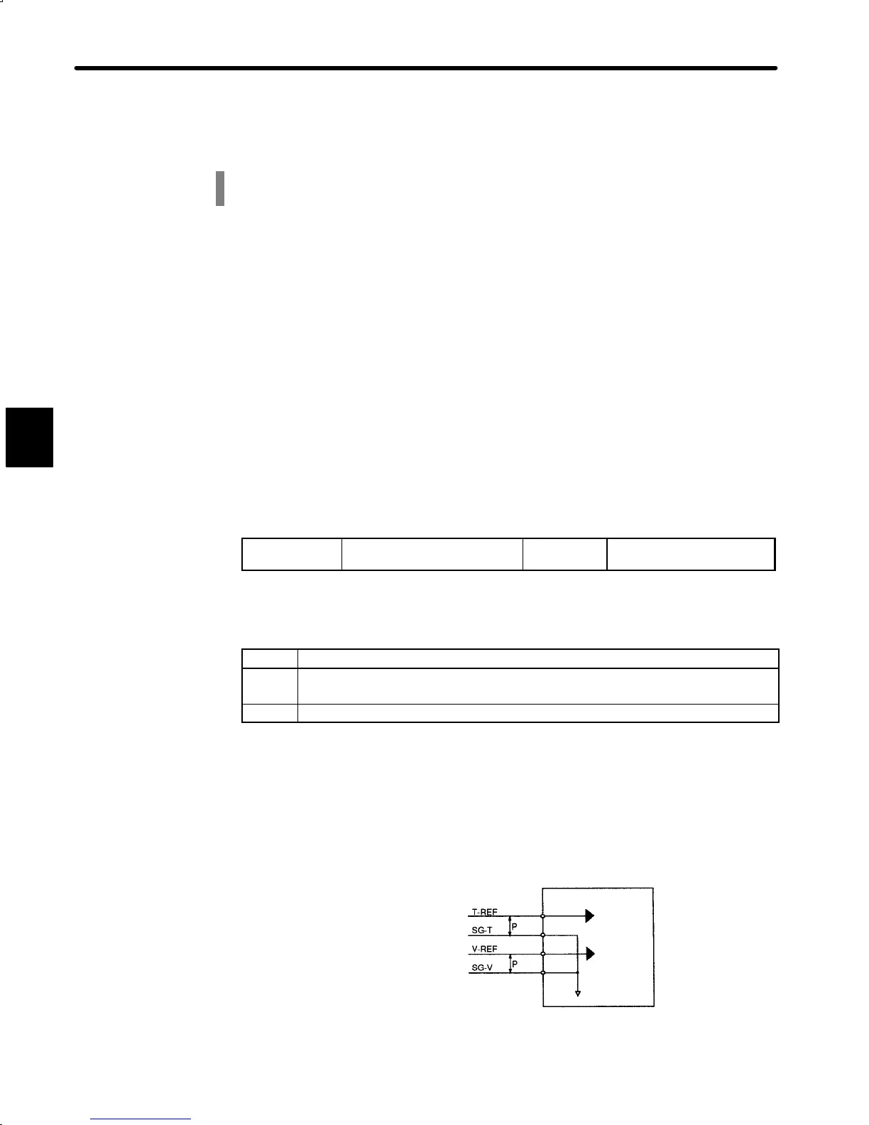
2) Input a speed reference by using the following input signal “speed reference input.” Since
this signal can be used in different ways, set the optimum reference input for the system
to be created.
Torque reference input
(analog voltage input)
Speed reference input
(analog voltage input)
Servopack
Torque
reference
Speed
reference
↕P: Represents twisted-pair cables
1CN-9
1CN-10
1CN-5
1CN-6
3