BASIC USES OF Σ-SERIES PRODUCTS
2.3.2 Main Circuit Wiring and Power ON Sequence
28
2.3.2 Main Circuit Wiring and Power ON Sequence
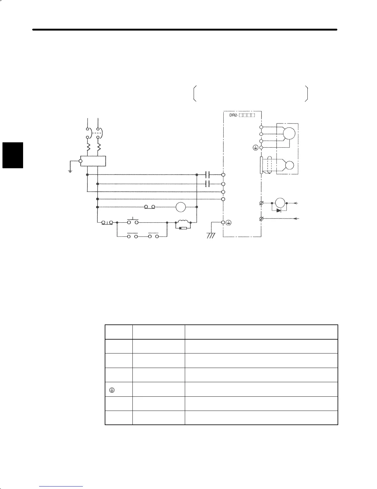
1) The following diagram shows a typical example of wiring the main circuit for Σ-Series
products:
1MCCB: Circuit breaker
1FIL: Noise filter
1MC: Contactor
1Ry: Relay
1PL: Patrol light
1SUP: Surge suppressor
1D: Flywheel diode
For 100 V Type
Single-phase 100 to 115 VAC 50/60 Hz
Single-phase 200 to 230 VAC 50/60 Hz
+ 10
–15
%
,
+ 10
–15
%
,
1MCCB
RT
1FIL
Main Power
OFF
ON
1MC
1Ry
1MC
1SUP
1PL
L1
ALM+
U
V
W
Servopack DR2
1MC
L2
L
N
1Ry
ALM-
A
B
C
D
M
PG
1Ry
31
32
1CN
1D
+24V
0
24
V
2) The following table shows the name and description of each main circuit terminal:
Terminal
Symbol
Name Description
L1, L2
Main circuit AC
input
Single-phase 200 to 230 VAC , 50/60Hz*
1
+ 10
–15
%
L, N
Control power
supply input
Single-phase 200 to 230 VAC , 50/60Hz*
1
+ 10
–15
%
U, V, W
Motor connection
Connects terminal U to motor terminal (red), V to (white)
and W to (blue).
×2
Ground terminal
Connects to ground and motor terminal (for ground and
motor grounding)
Y3, Y4
Regenerative
resistor connection
Regenerative resistor connection (External connection is not
normally required.)*
2
+, −
Regenerative unit
connection
Regenerative unit connection terminal (Connection is not
normally required.)*
3
*1 For 100 V power supply: Single-phase 100 to 115 VAC
+ 10
–15
%
, 50/60Hz
*2 Provided only for types 400W, 750W (200VAC) and 200W, 300W (100VAC).
*3 Provided only for types 30W to 200W (200VAC).
2

 Loading...


