APPLICATIONS OF Σ-SERIES PRODUCTS
3.7.5 Using Running Output Signal
136
Note When output signals CLT
+ and CLT- are used as the speed coincide output, set the following
memory switch (Cn-01 bit4) to 1.
Cn-01 Bit 4
CLT+, CLT- Output Signals
Selection
Factory
Setting: 0
For Speed/Torque Control
and Position Control
Sets the output conditions for output signals CLT+ (1CN-25) and CLT- (1CN-26).
Setting Meaning
0
Uses CLT+, CLT- output signals as a torque limit
output signal.
Refer to 3.1.3 for details.
1
Uses CLT+, CLT- output signals as a speed
coincide output signal.
Bit 4 of memory switch Cn-01
Torque
limit
detection
Speed
coincide
When CLT+, CLT- output
signals are changed, the
following bit data are also
changed:
• Status indication mode bit
data
• Monitor mode Un-05 bit 4
CLT+
CLT
-
(1CN-25)
(1CN-26)
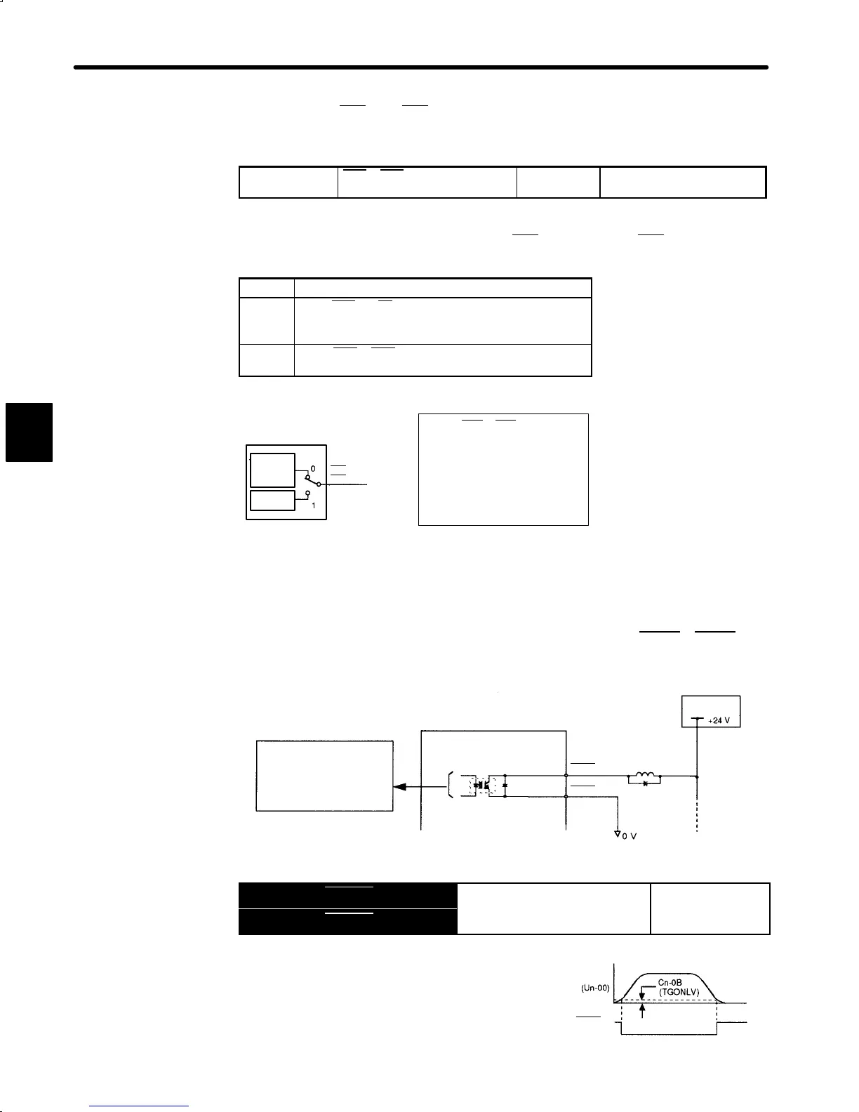
3.7.5 Using Running Output Signal
1) This section describes how to wire and use contact output signals TGON+, TGON-asa
running output signal. This signal indicates that a servomotor is currently running.
Photocoupler Output
Per output:
Maximum operation
voltage: 30 VDC
Maximum output
current: 50 mADC
Servopack
I/O power
supply
1CN-27
1CN-28
TGON+
TGON-
Output → TGON+ 1CN-27
Running Output (Brake Interlock
For Speed/Torque
Output → TGON- 1CN-28
Position Control
This output signal indicates that the motor is cur-
rently running.
It is used as an external interlock.
3
Motor
speed
TGON+
(1CN-27)

 Loading...


