3.7 Forming a Protective Sequence
137
ON
status:
Circuit between 1CN-27 and 1CN-28 is
closed.
1CN-27 is at low level.
Motor is running.
(Motor speed is greater than the preset
value.)
OFF
status:
Circuit between 1CN-27 and 1CN-28 is
open.
1CN-27 is at high level.
Motor is stopped.
(Motor speed is below the preset value.)
Preset value: Cn-0B (zero-speed level)
Note This function is changed to another function depending on the setting of bit E of
memory switch Cn-01.
2) To use TGON
+, TGON- as a running output signals, set the following memory switch to
“0.”
Cn-01 Bit E
TGON+, TGON- Output
Signals Selection
Factory
Setting: 0
For Speed/Torque Control
and Position Control
This memory switch is used to set output condi-
tions for output signals TGON
+, TGON-
(1CN-27).
When TGON
+, TGON- signals are changed, the following bit
data are also changed:
• Status indication mode bit data
• Monitor mode Un-05 bit 4
Setting Meaning
Uses TGON+, TGON- as a running output signals.
TGON
+, TGON- compare motor speed with the value set in Cn-0B (TGONLV).
0
Motor speed ≥ preset value Closes circuit between 1CN-27
and 1CN-28.
Motor speed < preset value Opens circuit between 1CN-27
and 1CN-28.
1
Uses TGON+, TGON- as a torque limit output signal.
For details, refer to 3.4.4.
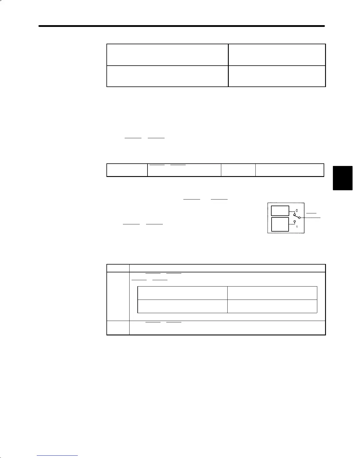
3
Memory switch
Cn-01 bit E
Rotation
detection
Brake
interlock
output
TGON+
(!CN-27)

 Loading...


