3.2 Setting User Constants According to Host Controller
65
→ Input V-REF 1CN-5
Speed Reference Input For Speed/Torque
Control Only
→ Input SG-V 1CN-6
Signal Ground for Speed
Reference Input
For Speed/Torque
Control Only
Use these signals when speed control is selected
(memory switch Cn-02 bit B = 0).
For ordinary speed control, always wire the V-
REF and SG-V terminals.
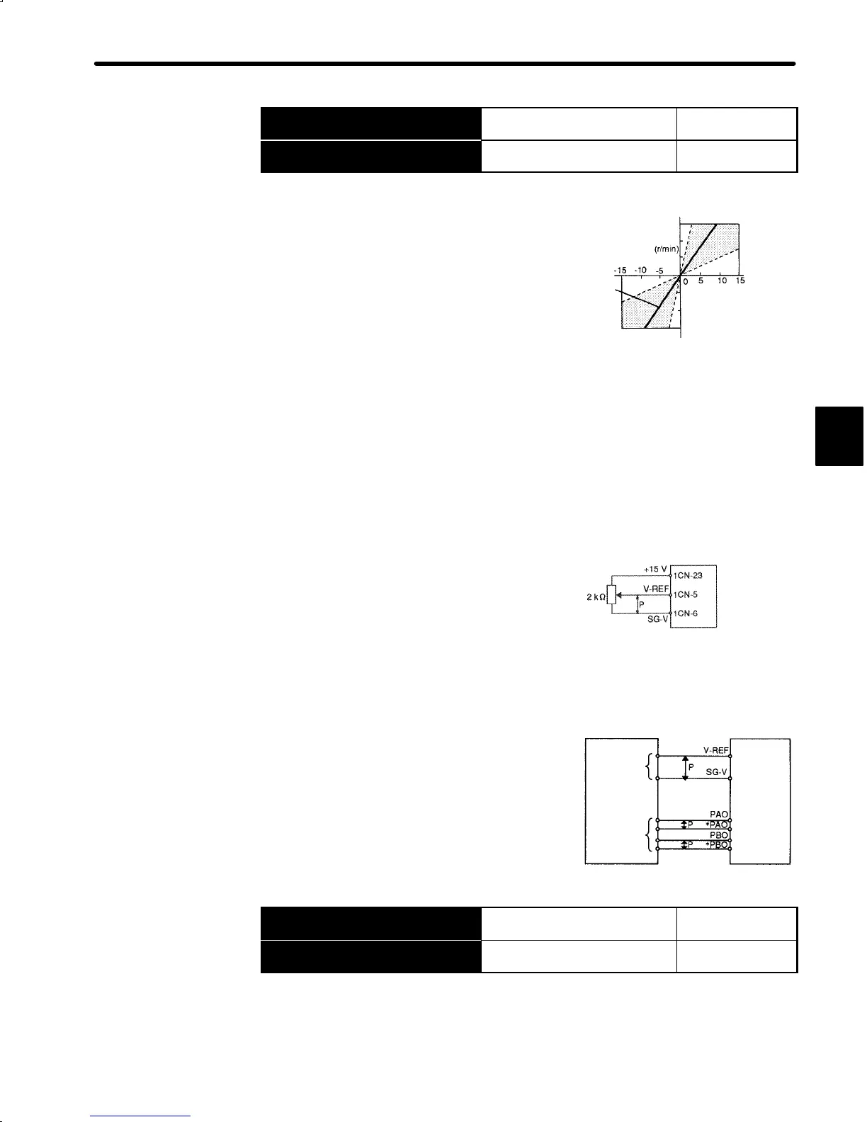
Motor speed is controlled in proportion to the input
voltage between V-REF and SG-V.
• Standard Setting:
Cn-03 = 500: This setting means that 6 V is equivalent to rated speed (3,000 r/min)
Examples:
+6 V input → 3000 r/min in forward direction
+1 V input → 500 r/min in forward direction
−3 V input → 1500 r/min in reverse direction
User constant Cn-03 can be used to change the voltage input range.
• Example of Input Circuit
(See the figure on the right)
For noise control, always use twisted-pair
cables.
Recommended Variable Resistor for Speed Setting:
Type 25HP-10B manufactured by Sakae Tsushin Kogyo Co., Ltd.
When position control is performed by a host con-
troller such as a programmable controller.
Connect V-REF and SG-V to speed reference
output terminals on the host controller. In this
case, adjust Cn-03 according to output voltage
specifications.
Output → +15V 1CN-23
+15V power supply for
speed/torque control
For Speed/Torque
Control Only
Output → -15V 1CN-24
-15V power supply for
speed/torque control
For Speed/Torque
Control Only
Power output for speed/torque control.
Max. output current is 30mADC.
3
Reference
speed
Standard
setting
Input voltage (V)
Set the slope in
Cn-03 (VREFGN).
4500
3000
1500
-1500
-3000
-4500
Servopack
Host controller Servopack
Speed
reference
output
terminals
Feedback
pulse input
terminals
↕P: Represents twisted-pair cables
1CN-5
1CN-6
1CN-33
1CN-34
1CN-35
1CN-36

 Loading...


