3.4 Setting Stop Mode
111
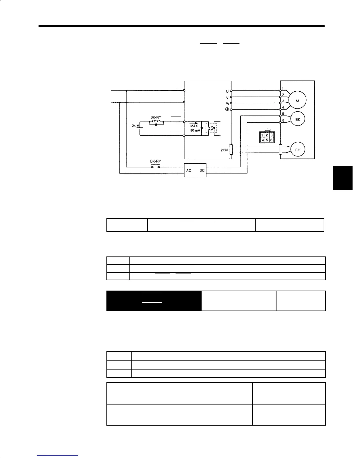
2) Use Servopack contact output-signal TGON+, TGON- and brake power supply to form a
brake ON/OFF circuit.
An example of standard wiring is shown below.
Power supply
Servopack Servomotor with brake
Motor plug
Blue or
yellow
Red
White Black
Brake power supply
BK-RY: Brake control relay
Brake power supply has two types (200 V, 100 V).
TGON-
TGON+
L
N
1CN-27
1CN-28
Set the following memory switch to select the brake interlock output.
Cn-01 Bit E
Selection of TGON+, TGON-
Signals
Factory
Setting: 0
For Speed/Torque Control
and Position Control
Set bit E of Cn-01 to 1 to select the brake interlock output.
Setting Meaning
0 Uses the TGON+, TGON- signals as the running output.
1 Uses the TGON+, TGON- signals as the brake interlock output.
Output → TGON+ 1CN-27
Brake Interlock Output, etc. For Speed/Torque
Output → TGON- 1CN-28
on
ro
an
Position Control
This output signal controls the brake when a motor with brake is used. This signal termi-
nal need not be connected when a motor without brake is used.
Related User Constants
Cn-12 Time delay from brake signal until servo OFF
Cn-15 Speed level for brake signal output during operation
Cn-16 Output timing of brake signal during motor operation
ON Status:
Circuit between 1CN-27 and 1CN-28 is closed.
1CN-27 is at low level.
Releases the brake.
OFF Status:
Circuit between 1CN-27 and 1CN-28 is open.
1CN-27 is at high level.
Applies the brake.
3

 Loading...


