3.6 Minimizing Positioning Time
127
Cn-0C
TRQMSW Mode Switch
(Torque
Reference)
Unit: % Setting
Range: 0
to 800
Factory
Setting:
200
For
Speed/Torque
Control and
Position Control
Cn-0D
REFMSW Mode Switch
(Speed
Reference)
Unit:
r/min
Setting
Range: 0
to 4500
Factory
Setting: 0
For
Speed/Torque
Control and
Position Control
Cn-0E
ACCMSW Mode Switch
(Acceleration
Reference)
Unit: 10
(r/min)/s
Setting
Range: 0
to 3000
Factory
Setting: 0
For
Speed/Torque
Control and
Position Control
Cn-0F
ERPMSW Mode Switch
(Error Pulse)
Unit:
Refer-
ence
Unit
Setting
Range: 0
to 10000
Factory
Setting: 0
For Position
Control Only
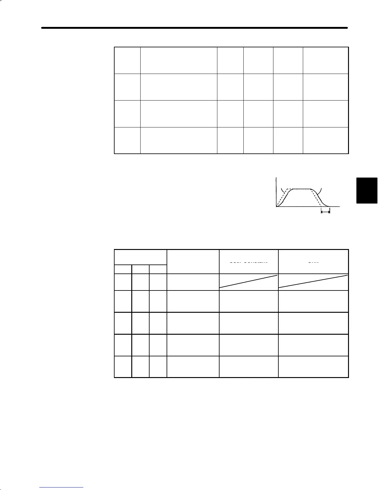
Mode switch is used to reduce settling time and
suppress undershoot when the motor stops. It
switches PI control to P control when certain
conditions are met.
The Servopack allows use of four different types of mode switch. To select a mode switch,
set bits B, C and D of memory switch Cn-01.
Memory Switch
Cn-01
Mode Switch
User Constant Unit
Bit D Bit C Bit B
e
ng
− − 1
Does not use
mode switch.
0 0 0
Uses torque refer-
ence as a detec-
tion point.
Cn-0C
Percentage of rated
torque: %
0 1 0
Uses speed refer-
ence as a detec-
tion point.
Cn-0D Motor speed: r/min
1 0 0
Uses acceleration
reference as a
detection point.
Cn-0E
Acceleration reference in-
side the DR2 Servopack:
10 (r/min)/s
1 1 0
Uses error pulse
as a detection
point.
Cn-0F Reference unit
User constant Cn-0F is for position control only.
3
Speed
Reference
Actual motor
operation
Time
Settling time

 Loading...


