3.8 Special Wiring
143
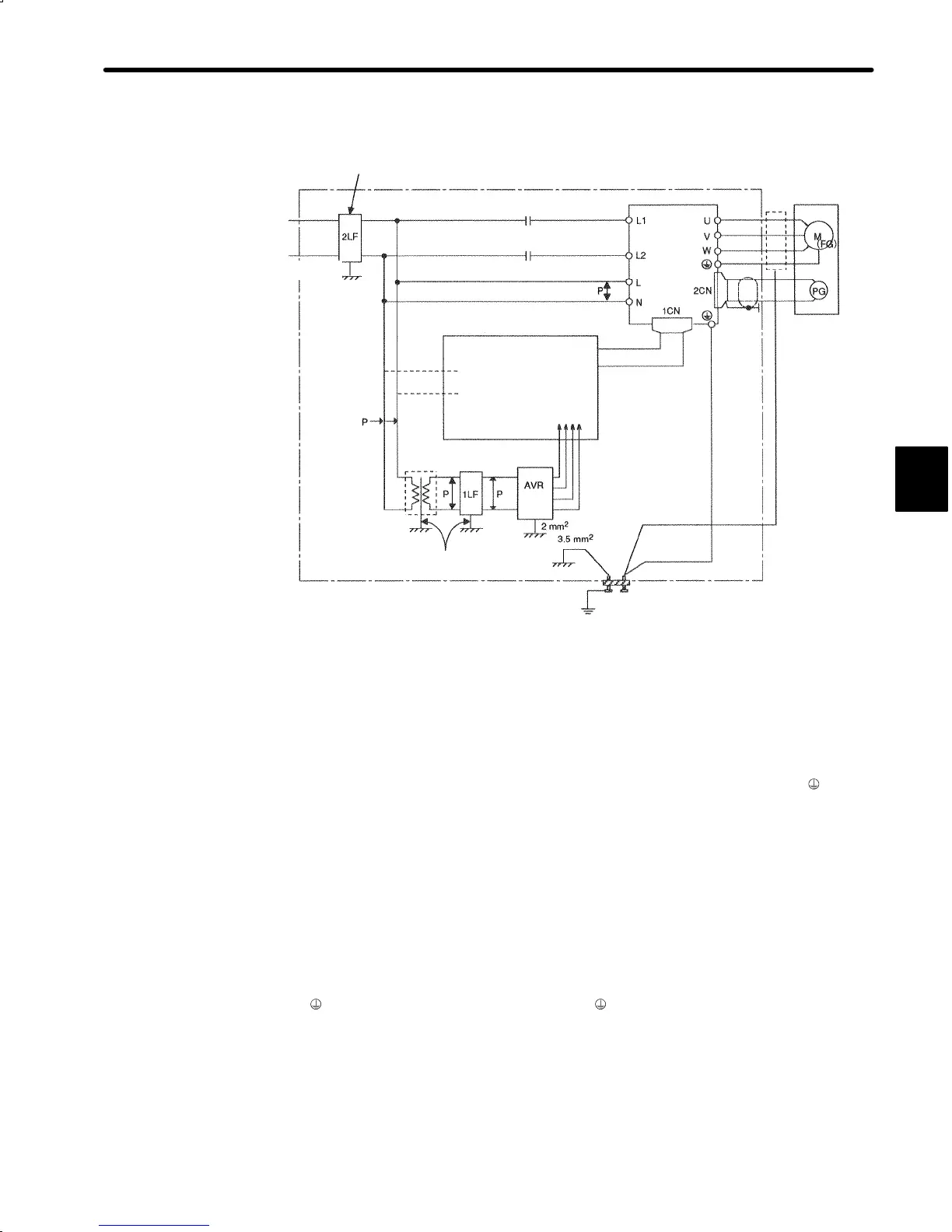
c) The following is an example of wiring for noise control.
Noise filter
*
1
Servomotor
(Red)
(White)
(Blue)
(Green)
DR2
Servopack
(Casing)
• Operation relay se-
quence
• Signal generation cir-
cuit (provided by cus-
tomer)
Wire with a thickness of
3.5 mm
2
or more
Ground plate
Ground: one-line grounding
(at least class 3 grounding)
(Casing)
(Casing)
(Casing)
(Casing)
3.5 mm
2
or more
100 or
200 VAC
3.5 mm
2
or more
Motor
output
line
shield
*2
3.5 mm
2
or more
* 1 When using a noise filter, always observe the following wiring instructions:
*2 Normally, motor output line shield is not required.
Note
1 For a ground wire to be connected to the casing, use a thick wire with a thick
ness of at least 3.5 mm
2
(preferably, plain stitch cooper wire).
However, be aware that max. connectable size of ground terminal
of
Servopack is 2.5mm
2
.
2 For wires indicated by P↕, use twisted-pair cables whenever possible.
2)
Correct Grounding
• Always ground the motor ground terminal.
Always connect servomotor ground terminal FG (green) to the Servopack ground termi-
nal
. Be sure to ground the ground terminal .
• If the servomotor is grounded via the machine, a switching noise current will flow from
the Servopack power unit through motor stray capacitance. The above grounding is re-
quired to prevent the adverse effects of switching noise.
• If the reference input line receives noise, do the following.
3

 Loading...


